Performance Tests
HP E-Series Power Sensor Functional Test
HP EPM-441A/442A Service Guide 2-17
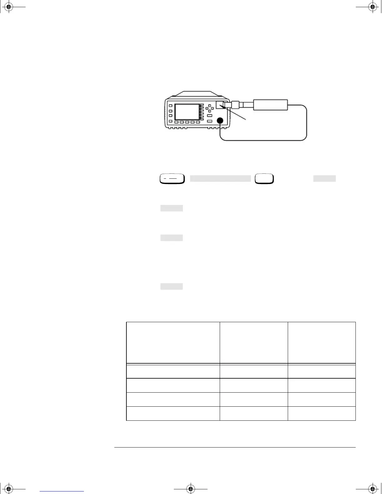
6. Connect the 30 dB attenuator as shown in Figure 2-5.
Figure 2-5: Sensor Functional Test Setup with Attenuator
7. Press , , , and select to
“LOWER”. This switches to the power sensor’s low range.
8. Verify that the display reads -30 dBm
±1 dB. Record the reading.
9. Press and set to “UPPER”. This switches to the power
sensor’s upper range.
10. Verify that the display reads -30 dBm
±1 dB. Record the reading.
11. Press and set to “LOWER”.
12. Disconnect the 30 dB attenuator and reconnect as shown in
Figure 2-4.
13. Verify that an overload error is displayed on the status line at the
top of the power meter’s display.
14. Press and set to “UPPER”.
15. Verify that the display reads 0 dBm
±1 dB. Record the reading.
Table 2-5: Functional Test Result
Test
Channel A
Overload Error
Channel B
Overload Error
(HP EPM-442A
Only)
Low Range, 30 dB pad
Upper Range, 30 dB pad
Low Range, no pad
High Range, no pad
Power Meter
HP E-Series
Power Sensor
HP 11708A
30 dB ATTENUATOR
CHANNEL A
HP 11730A
System
Inputs
Input Settings
More
Range
Range
Range
Range
4402serv.book Page 17 Monday, March 11, 2002 11:34 AM