Replaceable Parts
Assembly and Disassembly Guidelines
5-14 HP EPM-441A/442A Service Guide
Removing the A3 Front Panel Assembly
1. Disconnect the following cables from the A2 processor assembly:
■ power reference semi-rigid (When replacing use the torques
detailed on page 5-17.)
■ front panel keypad
■ front panel LCD
Note Care should be taken when disconnecting the front panel
keyboard and LCD. Remove the cables by pulling straight up from
the connectors.
2. Disconnect the flex circuit from the measurement assembly.
Note Care should be taken when disconnecting the flex circuit from the
measurement assembly.
The flex circuit assembly is released by pushing the connector tab
forward and lifting.
To replace the flex circuit, loop it as shown on page 5-16, and
connect the flex circuit as shown in the figures on page 5-11.
3. Remove the center screw from the right hand side of the front
panel.
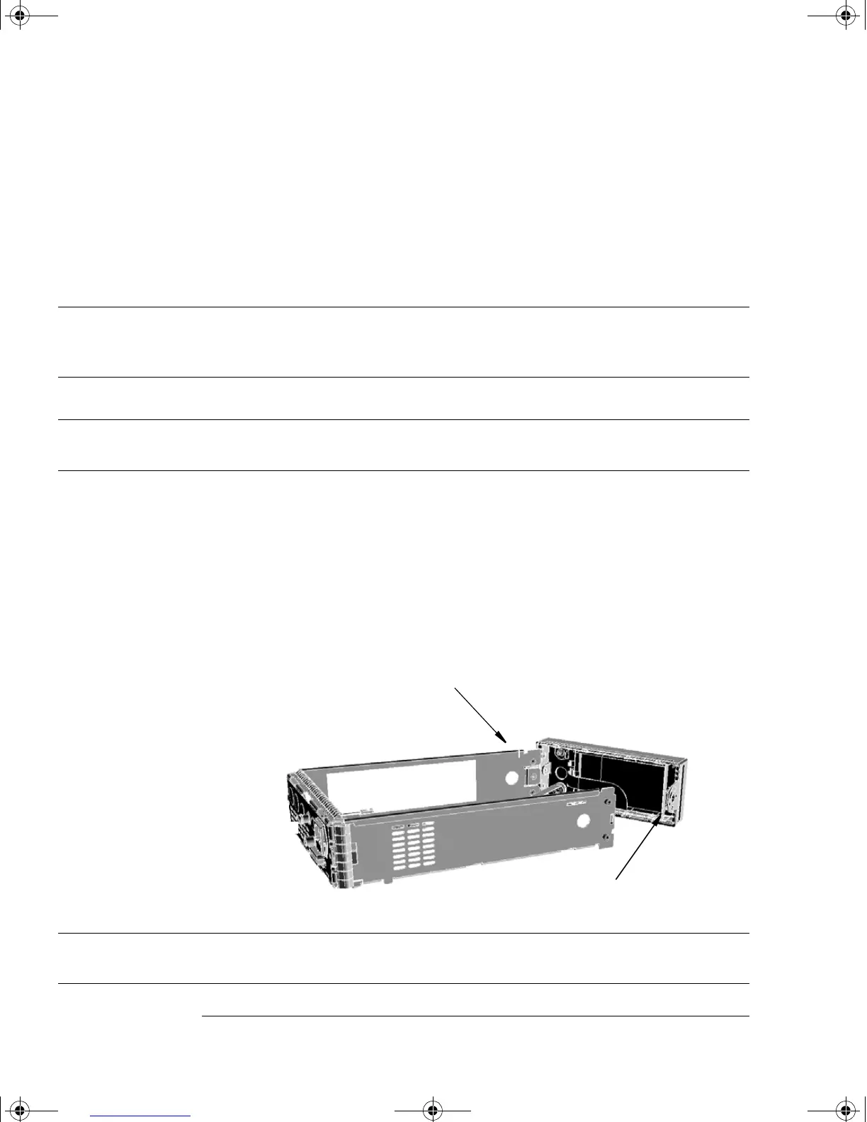
4. Remove the front panel by pressing in the metal tab on the front
panel as shown and push down on the side of the chassis until the
standoffs are cleared from the holes.
Note After replacing a front panel assembly, the display brightness and
contrast must be adjusted. Refer to Chapter 3 “Adjustments”.
tab
screw
4402serv.book Page 14 Monday, March 11, 2002 11:34 AM