Adjustments
Power Reference Oscillator Level Adjustment
3-10 HP EPM-441A/442A Service Guide
10. Turn the power reference on by pressing
■ , on the HP EPM-441A.
■ , , , on the
HP EPM-442A.
11. Record the reading on the DVM to two decimal places. This is
V
comp
.
■ V
comp
_____________V
12. Reconnect the negative lead to the V
RF
connector on the rear panel
of the HP 432A. The DVM is now set up to measure V
1
which
represents the power reference oscillator output level.
13. Calculate the required value of V
1
using equation 2.
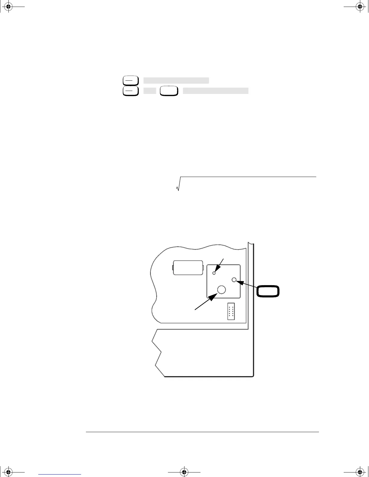
14. Remove the power meter’s cover and adjust A2R90 until the DVM
indicates the calculated value of V
1
. Refer to Figure 3-4 for the
position of A2R90.
Figure 3-4: A2R90 Adjustment Location
Zero
Cal
Power Ref Off On
Zero
Cal
Cal
More
Power Ref Off On
V
1
V
comp
V
0
V
comp
2
10()
3–
– 4R
()CalibrationFactor()–+=
BT1
A2R90
A2L9
A2J13
J12
Front Panel
A2 Assembly
4402serv.book Page 10 Monday, March 11, 2002 11:34 AM