Component identification
This chapter describes the external and internal server features and components.
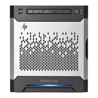
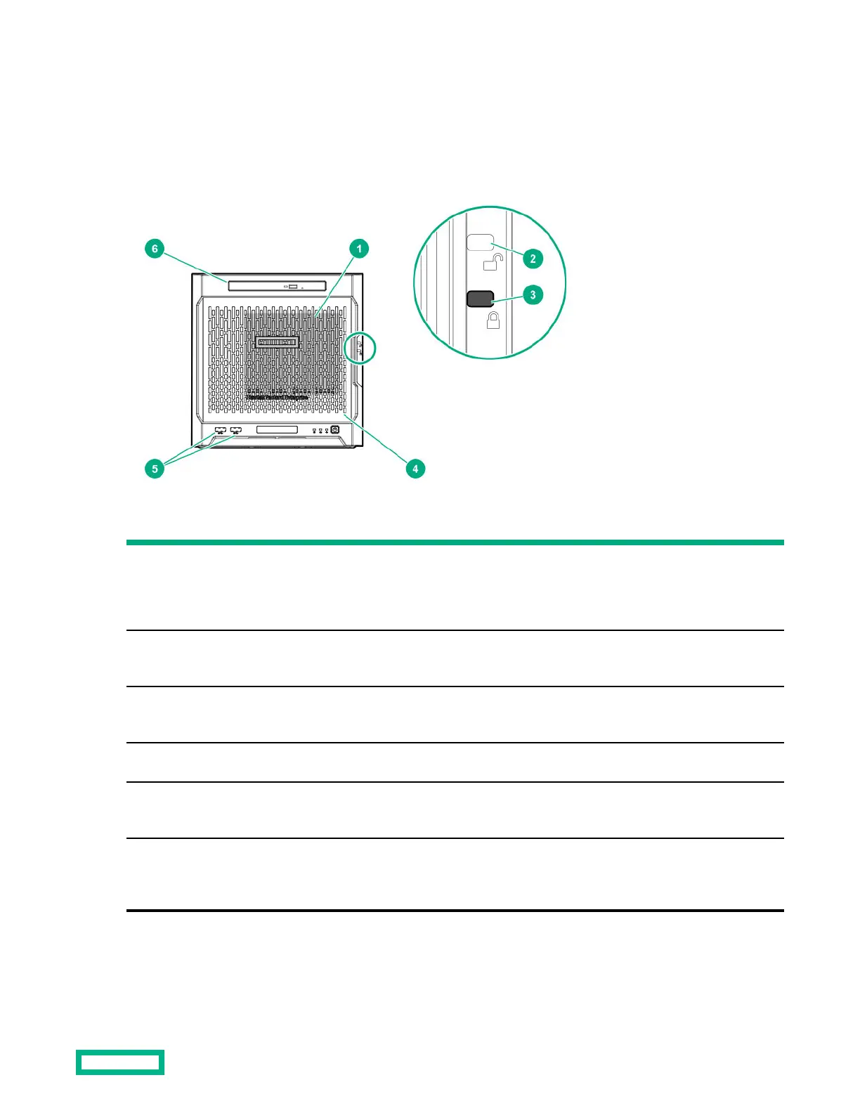
Front panel components
Item Component Description
1 Drive bays (4, behind the front bezel) By default, the drive bays support 35-inch LFF SATA drives.
To support 25-inch SFF drives, install the SFF drive converter
option.
2 Front bezel unlock indicator To remove the front bezel from the chassis, this groove must show
the blue indicator.
3 Front bezel lock indicator To lock the front bezel in the chassis, this groove must show the blue
indicator.
4 Front bezel To access the front drive bays, remove this bezel.
5 USB 30 ports (2) Connect USB 30 devices to these ports. USB 30 support after POST
varies by operating system.
6 Media bay When the relevant enablement options kits are installed, this bay
supports either a slim-type optical disc drive or solid-state drive
option.
Component identification 6
 Loading...