2-25
Installing the Switch
Installation Procedures
Installing the Switch
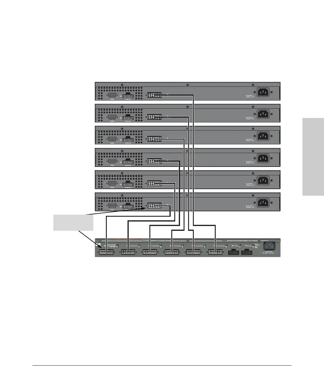
The following illustration shows an example of connectivity between an RPS/
EPS device and six switch devices as a redundant AC power supply.
The 600 RPS/EPS can provide backup power for up to six switches. The 600
RPS/EPS can supply power to only one connected and failed switch at a time.
In the illustration above, the switch connected to RPS port 1 has the highest
priority and the switch connected to RPS port 6 has the lowest priority. When
multiple switches fail, a switch connected to a higher priority port always
receives power before a switch connected to a lower priority port.
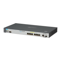
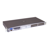
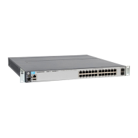
2650-PWR switches
600 RPS/EPS
Highest priority
connected to port 1
 Loading...