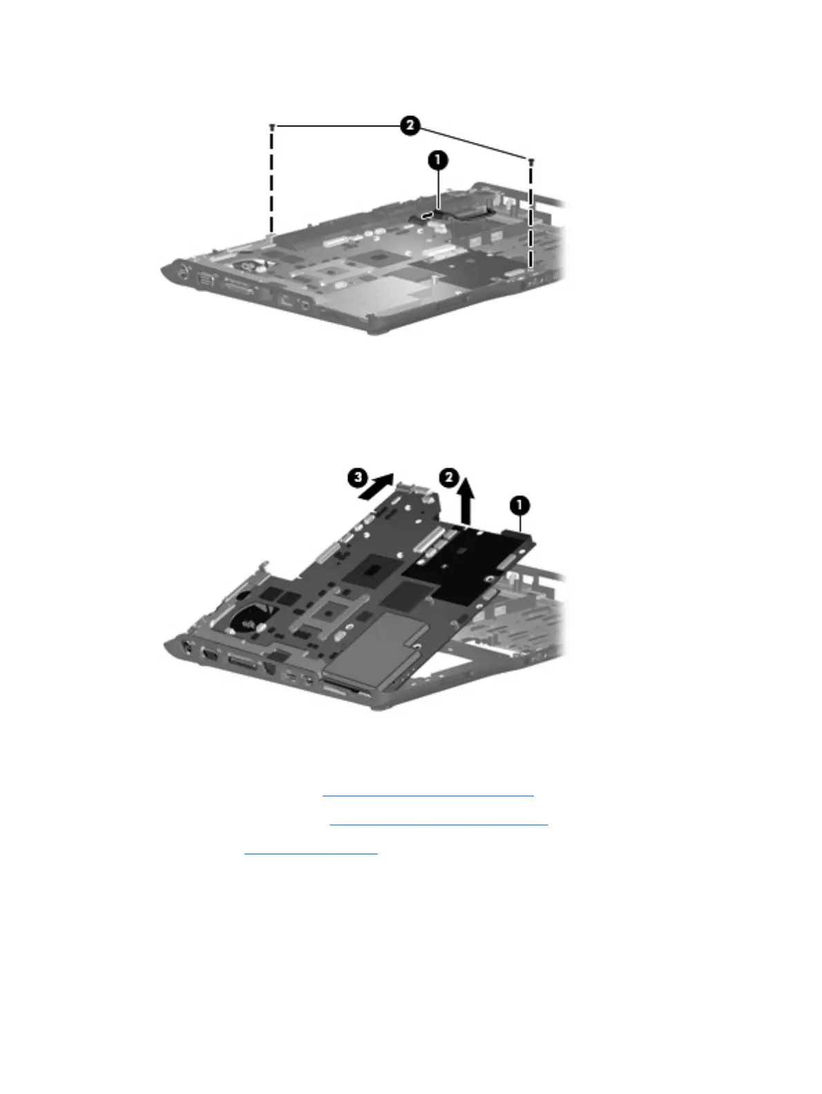
2. Remove the two Phillips PM2.5×5.0 screws (2) that secure the system board to the computer.
3. Use the optical drive connector (1) to lift the right side of the system board until it rests at an angle.
4. Release the system board (2) by sliding it to the right at an angle until the connectors on the left side
of the system board disengage from the base enclosure.
5. Remove the system board (3).
When replacing the system board, be sure that the following components are removed from the defective
system board and installed on the replacement system board:
●
ExpressCard assembly (see
ExpressCard assembly on page 94)
●
Fan/heat sink assembly (see
Fan/heat sink assembly on page 96)
●
Processor (see
Processor on page 99)
Reverse the preceding procedure to install the system board.
92 Chapter 4 Removal and replacement procedures
 Loading...