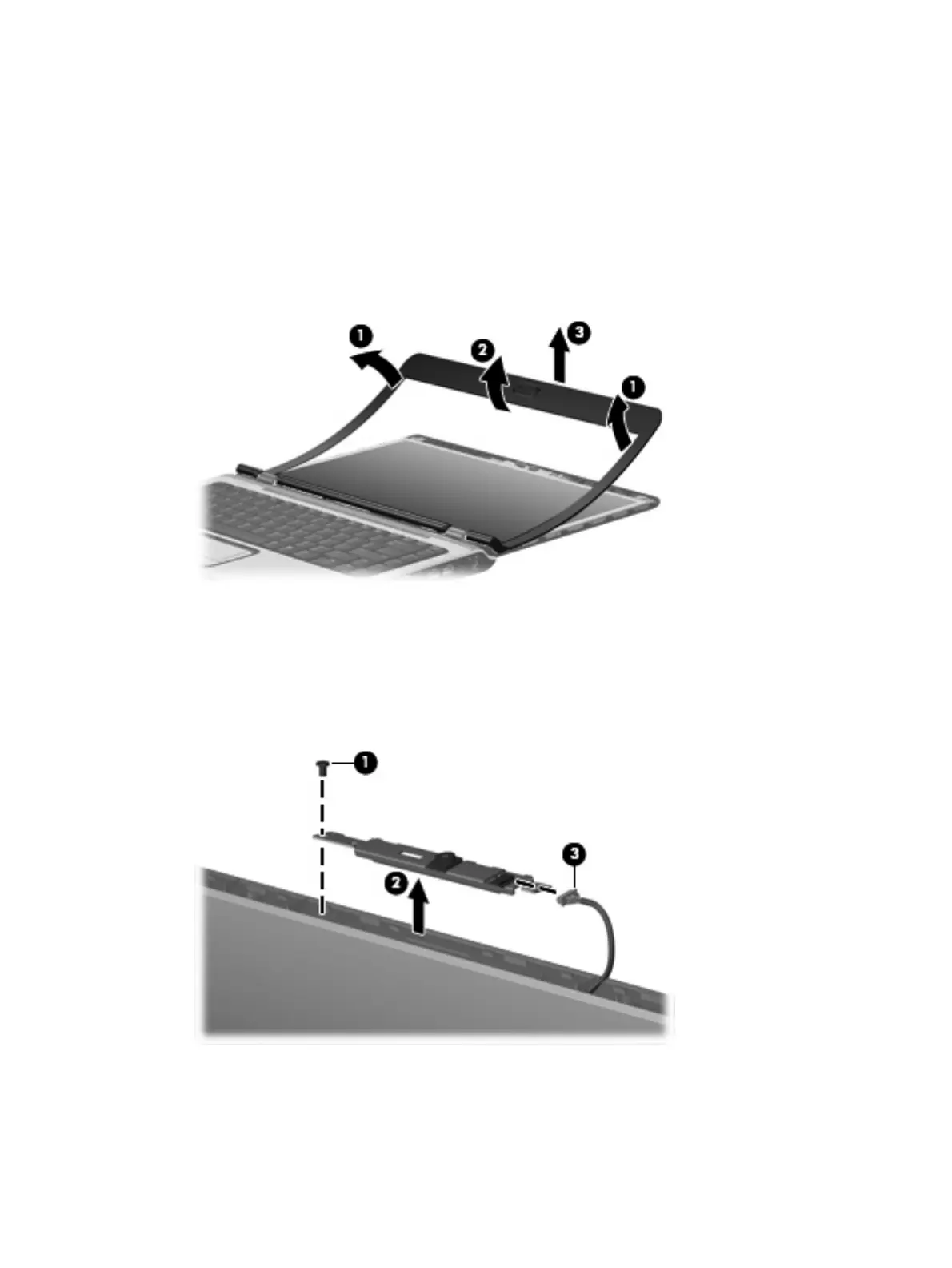
6. Release the display bezel top edge (3). Display bezels are available using the following spare part
numbers:
●
448607-001 (for use only with computer models that are equipped with a camera module;
includes openings for camera module and microphones)
●
448606-001 (for use only with computer models not equipped with a camera module; includes
openings for microphones)
●
451907-001 (for use only with computer models with Intel processors sold at Best Buy; includes
openings for camera module and microphones)
7. Remove the Phillips PM2.5×4.0 screw (1) that secures the camera module assembly to the display
enclosure.
8. Release the camera module assembly (2) from the display enclosure as far as the camera module
cable allows.
9. Disconnect the camera module cable (3) from the camera module.
10.
Turn the camera module assembly upside down.
11. Remove the two Phillips PM2.0×3.0 screws (1) that secure the camera module to the camera module
bracket.
Component replacement procedures 49
 Loading...