4.
Open the display as far as possible.
5.
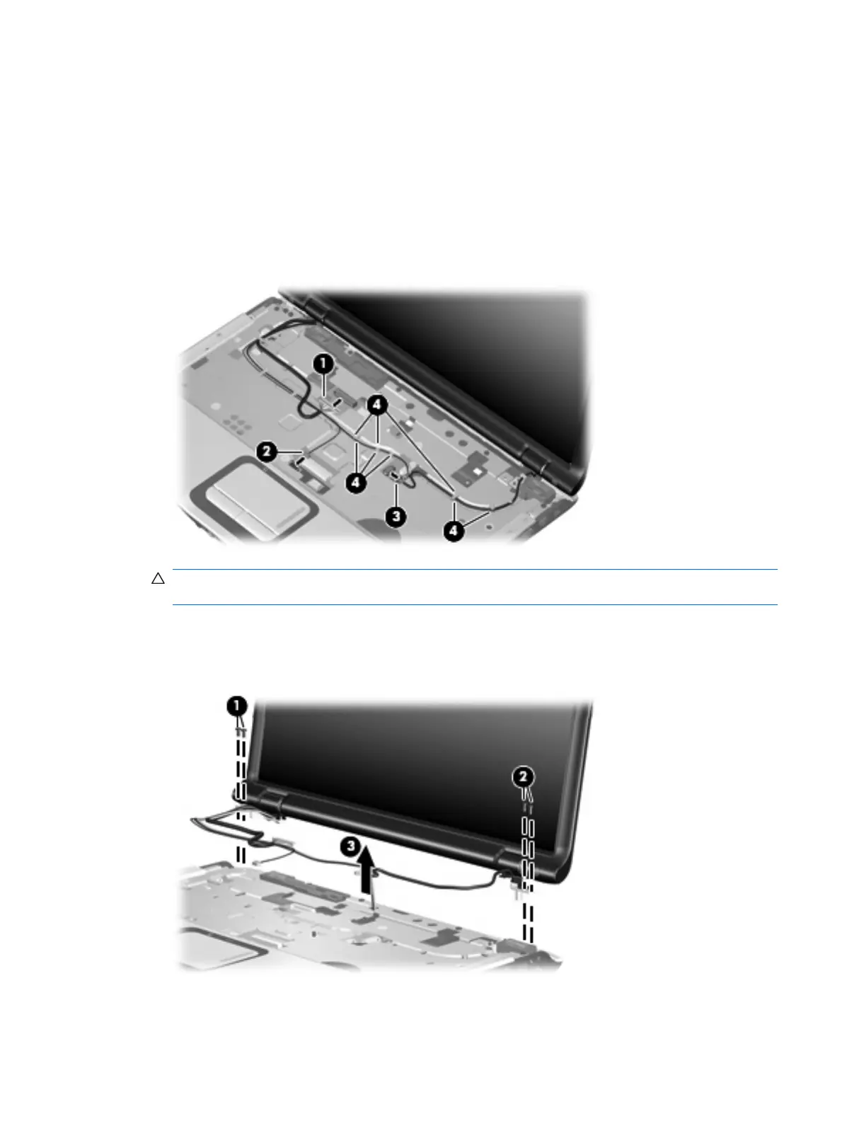
Disconnect the following cables:
(1) Display panel cable
(2) Camera module cable
(3) Microphone cable
6.
Remove the camera module, microphone, and wireless antenna cables from the hole in the system
board and the routing channels (4) built into the top cover.
CAUTION: Support the display assembly when removing the following screws. Failure to support
the display assembly can result in damage to the display assembly and other computer components.
7. Remove the two black Phillips PM2.5×5.0 screws (1) and the two Phillips PM2.5×7.0 screws (2)
that secure the display assembly to the computer.
8. Remove the display assembly (3).
Component replacement procedures 69
 Loading...