1-6
Introducing the Switch
Front of the Switch
Introducing the Switch
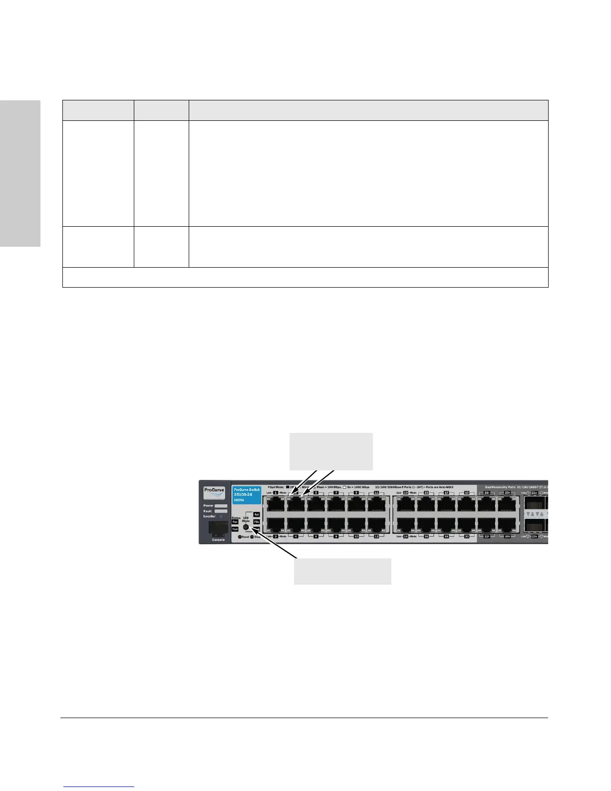
LED Mode Select Button and Indicator LEDs
To optimize the amount of information displayed for each of the switch ports
without overwhelming you with LEDs, the Switch 2510G Series devices use
two LEDs for each port. The operation of these LEDs is controlled by the LED
Mode select button, and the current setting is indicated by the LED Mode
indicator LEDs near the button. Press the button to step from one view mode
to the next.
Figure 1-1. LED Mode select on the Switch 2510G-24
Test
(green)
Off The normal operational state; the switch is not undergoing self test.
On The switch self test and initialization are in progress after the switch has been power
cycled or reset. The switch is not operational until this LED goes off. The Self Test LED
also comes on briefly when you “hot swap” a mini-GBIC into the switch; the mini-GBIC
is self tested when it is hot swapped.
flashing* A component of the switch has failed its self test. The status LED for that component,
for example an RJ-45 port, and the switch Fault LED will blink simultaneously.
Fan Status
(green)
On Normal operation, all fans are ok.
Flashing* One of the unit’s fans has failed. The switch Fault LED will be flashing simultaneously.
* The flashing behavior is an on/off cycle once every 1.6 seconds, approximately.
Switch LEDs State Meaning
Port LEDs
(two for each port)
Link and Mode
LED Mode select button
and indicator LEDs

 Loading...