2-18
Installing the Switch
Installation Procedures
Installing the Switch
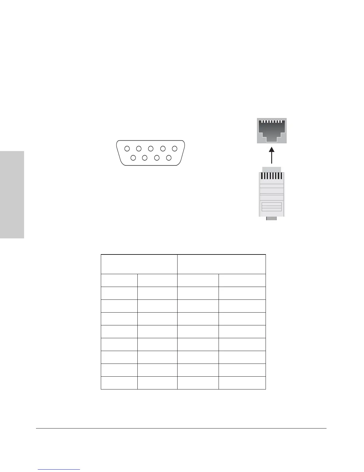
Console Cable Pinouts
The console cable has an RJ-45 male connector on one end and a DB-9 female
connector on the other end. Table 2-12 describes the mapping of the RJ-45 to
DB-9 pins.
Figure 2-11. RJ-45 to DB-9 pinouts
Table 2-12. Mapping of RJ-45 to DB-9
RJ-45 (Signal reference from
Chassis
DB-9 (Signal reference from PC)
RTS18CTS
TX_Debug 2 6 DSR
TXD 3 2 RXD
GND 4 5 GND
DCD 5 1 DCD
RXD 6 3 TXD
RX_Debug 7 4 DTR
CTS87RTS
9RI
5
4321
9
876
12345678
12345678
 Loading...