Index – 5
Index
Proactive Network tools
diagnostics with … 4-8
R
rack
mounting precautions … 2-3
mounting the switch in … 2-11
recycle statements … D-1
regulatory statements … C-8
Reset button
description … 1-7
location on switch … 1-3, 1-7
restoring factory default configuration … 4-11
resetting the switch
factory default reset … 4-11
location of Reset button … 1-7
troubleshooting procedure … 4-9
S
safety and regulatory statements … C-1
safety specifications … A-2
segment switch
sample topology … 2-20
selecting the LED Mode display … 1-6
self test
Fault LED behavior … 2-11
LED behavior during … 2-10
Power LED behavior … 2-11
Self Test LED … 1-6
serial cable
for direct console connection … 2-17
slots for mini-GBICs
location on switch … 1-3
Spd LED … 1-5, 1-7
specifications
connectors … A-2
electrical … A-1
environmental … A-1
physical … A-1
safety … A-2
straight-through cable
pin-out … B-7, B-9
subnet mask
configuring … 3-3
summary
of cables used with the switch … 2-5
of switch installation … 2-4
switch
connecting to a power source … 2-14
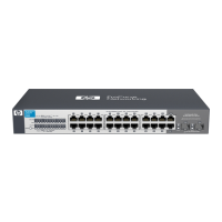
description … 1-1
downloading new software … 4-12
electrical specifications … A-1
environmental specifications … A-1
features … 1-9
front panel description … 1-3
included parts … 2-1
LED descriptions … 1-5
mounting in a rack or cabinet … 2-11
mounting on horizontal surface … 2-14
physical specifications … A-1
switch operation
verifying after installation … 2-9
Switch Setup screen … 3-2
configuring a subnet mask … 3-3
configuring an IP address … 3-3
field descriptions … 3-3
T
Telnet access to the console … 3-5
terminal configuration … 2-16
Test LED
behavior during factory default reset … 4-11
behavior during self test … 2-10
testing
checking the console messages … 4-9
checking the LEDs … 4-9
diagnostic tests … 4-9
end-to-end communications … 4-10
link test … 4-10
Ping test … 4-10
switch operation … 4-9
switch-to-device communications … 4-10
twisted-pair cabling … 4-10
tips for troubleshooting … 4-1
topologies
samples of … 2-19
 Loading...