Fan Sink (Thermal Module)
Description Spare part number
Fan sink (thermal module) for use in computers with discrete graphics 658987-001
Fan sink (thermal module) for use in computers with UMA graphics 658988-001
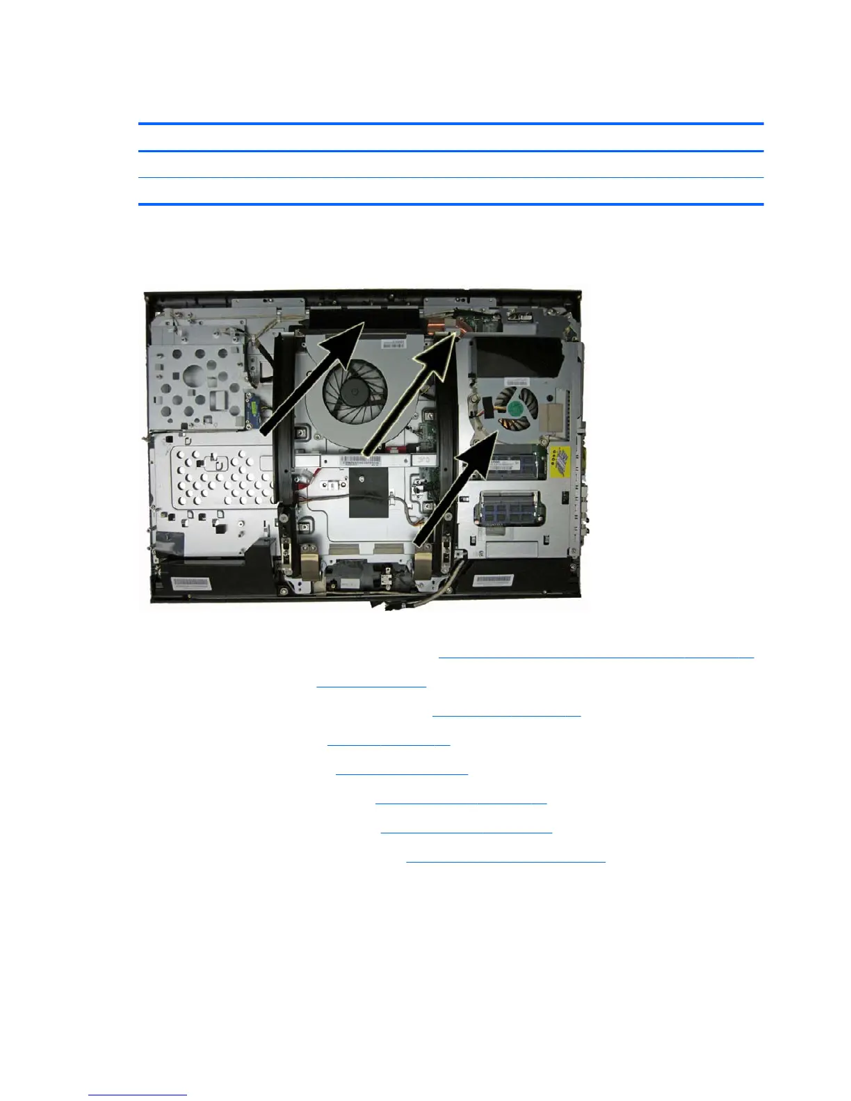
The fan sink is secured with four screws. You do not have to remove the chassis fan to remove the it.
Figure 7-60 Fan location
To remove the fan sink:
1. Prepare the computer for disassembly (see
Preparing to disassemble the computer on page 33).
2. Remove the stand (see
Stand on page 34).
3. Remove the right and left rear panels (see
Rear panels on page 46).
4. Remove the left cap (see
Left cap on page 60).
5. Remove the right cap (see
Right cap on page 66).
6. Remove the rear logo cover (see
Rear logo cover on page 71).
7. Remove the rear main frame (see
Main rear frame on page 74).
8. Remove the system board shield (see
System board shield on page 76).
9. In the order indicated by the numbers stamped into the heat sink, remove the four screws (1)
that secure the fan sink to the system board.
10. Disconnect the fan cable from the system board (2).
84 Chapter 7 Removal and Replacement Procedures