Do you have a question about the HP Z24n G3 and is the answer not in the manual?
Minimize risk of personal injury during service by following cautions and notes. Proper service methods are crucial for safe operation.
General service guidance for the monitor. Adherence to procedures and precautions is essential for proper service and to prevent damage.
Professional repairers need technical competence, compliance with regulations, and insurance for electrical equipment repair.
Understanding RoHS (Restriction of Hazardous Substance) requirements for electronics sold in the EU and other countries.
Manual contains general information with two service levels: cosmetic/appearance and circuit board/standard parts replacement.
Information on obtaining and applying firmware updates for the monitor from HP's support website.
Perform AC leakage current check on exposed parts before returning repaired products to ensure safety.
Details on screen size, resolution, panel type (IPS), color gamut, backlight, and viewing angles.
Lists video inputs (DisplayPort, HDMI) and USB hub ports (Type-B upstream, Type-A downstream).
Features a removable stand for flexible mounting and HP Quick Release 2 for easy attachment.
Supports VESA mounting brackets for wall, swing arm, or workstation attachment (100 x 100 mm).
Identifies OSD control, security slot, power switch, power connector, HDMI, DisplayPort, and USB ports on the rear panel.
Lists and describes major internal components such as LCM Module, chassis, power board, and interface board with item numbers.
Information on purchasing HP power boards, including spare part numbers and manufacturer part numbers.
Details on ordering specific connectors (HDMI, DP) by manufacturer, distributor part number, and required modifications.
Information for ordering USB-A and USB-B connectors, including necessary modifications and distributor part numbers.
Guides on preparing for disassembly, including reading safety info, cleaning the area, and gathering tools like screwdrivers and ESD protection.
Steps to remove the rear cover, involving detaching the stand base and releasing hooks.
Procedure to remove the power board after preparing the monitor and disconnecting cables.
Identifies the power board connector (CN801) and the location of the part number on the board.
Instructions on desoldering components from the power board using a soldering iron and absorber.
Lists connectors on the main board: HDMI, DP, USB-B, and USB-A, with their locations.
Steps to remove solder from HDMI connector pins using a soldering iron and de-soldering pump.
Procedure for melting solder on HDMI connector pins using a hot air gun for removal.
Steps to lift the old connector, place the new component, and solder it onto the PCB footprint.
Steps to remove solder from DP connector pins using a soldering iron and de-soldering pump.
Procedure for melting solder on DP connector pins using a hot air gun for removal.
Steps to lift the old connector, place the new component, and solder it onto the PCB footprint.
Steps to remove solder from USB-B connector pins using a soldering iron and de-soldering pump.
Steps to lift the old connector, place the new component, and solder it onto the PCB footprint.
Steps to remove solder from USB-A connector pins using a soldering iron and de-soldering pump.
Steps to lift the old connector, place the new component, and solder it onto the PCB footprint.
Steps to remove solder from USB-A connector pins using a soldering iron and de-soldering pump.
Steps to lift the old connector, place the new component, and solder it onto the PCB footprint.
Confirms functionality of HDMI, DP, DP out, and USB Hub after repair using specified tests and tools.
Lists common problems like blank screen or flashing video, with their causes and recommended solutions.
Addresses issues like low brightness, blurred image, and disconnected video cables with troubleshooting steps.
Covers input signal out of range, failure to enter sleep mode, and OSD/Power button lockout issues.
This document serves as a comprehensive Maintenance and Service Guide for the HP Z24n G3 monitor, providing essential information for trained service personnel. It outlines the device's functionalities, operational features, and detailed maintenance procedures, ensuring safe and effective servicing.
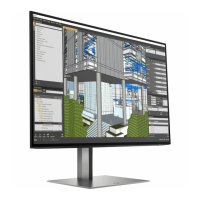
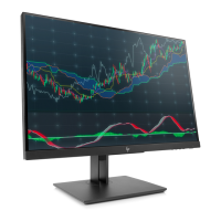
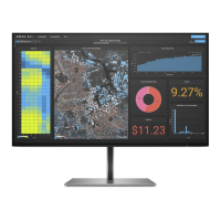
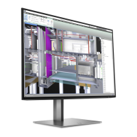
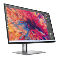
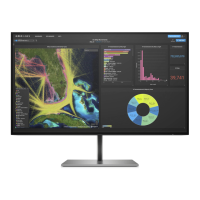
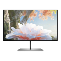
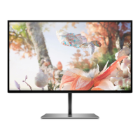
The HP Z24n G3 monitor is designed for a wide range of uses, offering a high-quality visual experience. Its display features include a diagonal viewable screen area with a specific resolution, supporting full-screen display for lower resolutions while maintaining the original aspect ratio through custom scaling. The monitor utilizes a Liquid Crystal Display (LCD) with active matrix and in-plane switching (IPS) technology, which contributes to wide viewing angles, allowing for clear visibility from various sitting or standing positions, or when moving from side to side. The nonglare panel, coupled with an LED backlight, further enhances viewing comfort by reducing reflections. A wide color gamut ensures coverage of sRGB color spaces, providing accurate and vibrant color reproduction.
Ergonomically, the monitor offers tilt, swivel, and height adjustment capabilities, allowing users to customize their viewing experience for optimal comfort. A notable feature is its pivot capability, which enables the monitor head to rotate from a landscape to a portrait orientation, catering to different content viewing needs. For enhanced multitasking, select models include Dual Picture in Picture (PiP) and Picture beside Picture (PbP) functionality, allowing DisplayPort and HDMI inputs to be viewed simultaneously in separate halves of the screen.
The monitor's user interface is managed through On-Screen Display (OSD) adjustments, available in multiple languages, facilitating easy setup and screen optimization. It also includes color space presets for sRGB and BT.709, offering quick adjustments for specific visual requirements. An energy saver feature is integrated to meet requirements for reduced power consumption, aligning with environmental standards. For physical security, a security cable slot is located on the rear, accommodating an optional security cable. Cable management features are also incorporated to help organize cables and cords, maintaining a tidy workspace.
Connectivity options are robust, including DisplayPort video input and output, with a DisplayPort cable typically included. It also features a High-Definition Multimedia Interface (HDMI) video input. For USB connectivity, select products are equipped with a USB hub that includes one USB Type-B port for connecting to the computer (upstream) and four USB Type-A ports for connecting to various USB devices (downstream). A USB Type-B-to-USB Type-A cable is usually provided. The monitor supports Plug and Play capability, simplifying setup with compatible operating systems.
The monitor stand is designed for flexibility, being removable to allow for alternative mounting solutions. It incorporates an HP Quick Release 2 device, enabling quick attachment of the monitor head to the stand with a simple click and easy removal via a sliding tab release. The monitor also features VESA® mounting bracket support (100 × 100 mm) for attaching the monitor head to a wall-mount device, swing arm, or workstation mounting bracket.
For maintenance and service, the guide emphasizes the importance of safety information and precautions. It specifies that only trained service personnel familiar with the product should perform service. Key safety measures include ensuring a dry and clean working environment, disconnecting power before opening the cabinet, and following ESD safety procedures when handling electrical components. The document also highlights the importance of using lead-free solder wire for repairs and matching capacitor polarities and specifications.
The guide details a structured approach to disassembly and reassembly, starting with preparation steps such as cleaning the work area and gathering necessary equipment like press fixtures, screwdrivers, knives, gloves, cleaning cloths, ESD protection, and a scraper bar. It provides step-by-step instructions for removing the rear cover, USB board, OSD key board, IO cover, and bracket assembly, as well as the bottom bezel assembly.
A significant part of the maintenance section is dedicated to power board and connector repair. It identifies the power board part numbers and provides instructions for locating the part number on the board and performing pin soldering. For connector repair, including HDMI, DisplayPort, USB-B, and USB-A connectors, the guide outlines a process involving using a soldering iron and de-soldering pump to remove solder, followed by a hot air gun to melt remaining solder, lifting the old connector, placing a new one, and then soldering it in place. The importance of matching the PCB footprint for new components is stressed.
After any repair, a function test is recommended to confirm that all monitor functions are working correctly. This includes tests for HDMI, DisplayPort, DisplayPort out, and USB Hub functionality. The guide also includes a support and troubleshooting section, listing common problems, their possible causes (e.g., disconnected power cord, monitor turned off, incompatible video card, low brightness, OSD lockout), and recommended solutions (e.g., connecting power, powering on the monitor, adjusting settings, replacing components). This comprehensive approach ensures that the monitor can be effectively maintained and repaired, extending its lifespan and ensuring continued optimal performance.
| HD type | WUXGA |
|---|---|
| Pixel pitch | 0.27 x 0.27 mm |
| Screen shape | Flat |
| Display diagonal | 24 \ |
| Display resolution | 1920 x 1200 pixels |
| Display technology | LED |
| Native aspect ratio | 16:9 |
| Vertical scan range | 50 - 60 Hz |
| Maximum refresh rate | 60 Hz |
| Viewable size, vertical | 324 mm |
| Contrast ratio (typical) | 1000:1 |
| Display number of colors | - |
| Display diagonal (metric) | 61 cm |
| Viewable size, horizontal | 518.4 mm |
| Display brightness (typical) | 350 cd/m² |
| Supported graphics resolutions | 640 x 480 (VGA), 800 x 600 (SVGA), 1024 x 768 (XGA), 1280 x 1024 (SXGA), 1280 x 720 (HD 720), 1280 x 800 (WXGA), 1440 x 900 (WXGA+), 1600 x 1200 (UXGA), 1600 x 900, 1680 x 1050 (WSXGA+), 1920 x 1080 (HD 1080), 1920 x 1200 (WUXGA) |
| HDMI | Yes |
| HDMI version | 1.4 |
| USB hub version | 3.2 Gen 1 (3.1 Gen 1) |
| DisplayPort version | 1.2 |
| Sustainability certificates | ENERGY STAR |
| Pivot angle | -90 - 90 ° |
| Tilt angle range | -5 - 20 ° |
| Number of OSD languages | 10 |
| Panel mounting interface | 100 x 200 mm |
| On Screen Display (OSD) languages | CHI (SIMPL), CHI (TR), DEU, DUT, ENG, ESP, FRE, ITA, JPN, POR |
| Operating temperature (T-T) | 5 - 35 °C |
| Storage relative humidity (H-H) | 5 - 95 % |
| Operating relative humidity (H-H) | 20 - 80 % |
| Package depth | 415 mm |
| Package width | 625 mm |
| Package height | 142 mm |
| Package weight | 7600 g |
| AC input voltage | 100 - 240 V |
| Energy efficiency scale | A to G |
| Power consumption (max) | 63 W |
| Power consumption (standby) | 0.5 W |
| Power consumption (typical) | 28 W |
| Product color | Silver |
| Heavy metals free | Hg (mercury) |
| Market positioning | Business |
| Harmonized System (HS) code | 85285210 |
| Depth (with stand) | 195 mm |
|---|---|
| Height (with stand) | 521.4 mm |
| Weight (with stand) | 4900 g |
| Depth (without stand) | 38.5 mm |
| Width (without stand) | 531.7 mm |
| Height (without stand) | 342.9 mm |