51
Configure a port-based multicast VLAN on Switch B to meet the following requirements:
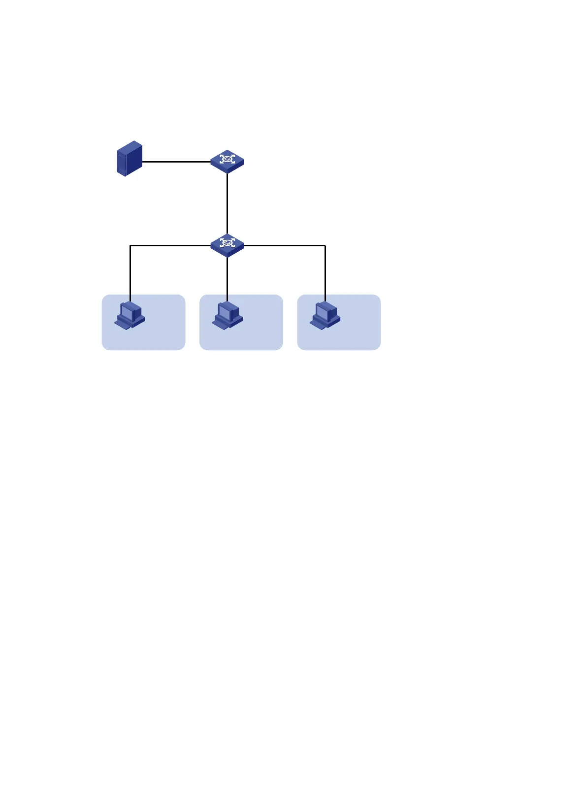
• Switch A sends multicast data to Switch B through the multicast VLAN.
• Switch B forwards the multicast data to the receivers in different user VLANs.
Figure 21 Network diagram
Configuration procedure
1. Configure Switch A:
# Enable IP multicast routing.
<SwitchA> system-view
[SwitchA] multicast routing
[SwitchA-mrib] quit
# Create VLAN 20, and assign GigabitEthernet 1/0/2 to this VLAN.
[SwitchA] vlan 20
[SwitchA-vlan20] port gigabitethernet 1/0/2
[SwitchA-vlan20] quit
# Assign an IP address to VLAN-interface 20, and enable PIM-DM on this interface.
[SwitchA] interface vlan-interface 20
[SwitchA-Vlan-interface20] ip address 1.1.1.2 24
[SwitchA-Vlan-interface20] pim dm
[SwitchA-Vlan-interface20] quit
# Create VLAN 10, and assign GigabitEthernet 1/0/1 to the VLAN.
[SwitchA] vlan 10
[SwitchA-vlan10] port gigabitethernet 1/0/1
[SwitchA-vlan10] quit
# Assign an IP address to VLAN-interface 10, and enable IGMP on this interface.
[SwitchA] interface vlan-interface 10
[SwitchA-Vlan-interface10] ip address 10.110.1.1 24
[SwitchA-Vlan-interface10] igmp enable
[SwitchA-Vlan-interface10] quit
2. Configure Switch B:
# Enable IGMP snooping globally.
Source
Receiver
Host A
VLAN 2
GE1/0/2
GE1/0/3
GE1/0/4
Switch B
IGMP querier
Switch A
1.1.1.1/24
Receiver
Host B
VLAN 3
Receiver
Host C
VLAN 4
GE1/0/1
GE1/0/1
Vlan-int10
10.110.1.1/24
GE1/0/2
Vlan-int20
1.1.1.2/24

 Loading...


