LP-551 Rev. 3.9.16
15
Undersized expansion tanks cause system water to be lost
from the relief valve, causing make-up water to be added.
Eventual boiler failure can result due to excessive make-
up water addition. SUCH FAILURE IS NOT COVERED BY
WARRANTY.
The expansion tank must be suitable for hot potable water
systems.
2. The expansion tank must be located as shown in
Applications, this manual, or following recognized design
methods. See expansion tank manufacturer’s instructions for
details.
Some local codes require back ow preventers on all incoming
water supplies. The hot water expansion tank must be listed
for potable water use. The expansion tank should be located
on the cold inlet piping close to the boiler.
Expansion Tank and Make-Up Water
1. Ensure that the expansion tank is sized to correctly handle
boiler and system water volume and temperature.
Expansion tanks must be sized according to total system
volume. This includes all length of pipe, all xtures, boilers,
etc. Failure to properly size for system expansion could result
in wasted time, money, possible property damage, serious
injury, or death.
Expansion Tank Sizing*
VWH Model Heat Exchanger Volume (Gallons)
220 2.6
299 / 301 3.1
399 3.7
Table 3 - *Add Required Storage Tank Gallon Size to Heat
Exchanger Volume - 60, 80, 119, and 175 Gallon Tanks Available
DO NOT install automatic air vents on closed type expansion
tank systems. Air must remain in the system and return to the
tank to provide an air cushion. An automatic air vent would
cause air to leave the system, resulting in improper operation
of the expansion tank.
E. Circulators
Every VWH system requires special attention to circulator size
to overcome pressure drop through the boiler and its related
piping. All circulators installed on the VWH system must be
designed for potable water installations. Boiler pressure drop
is detailed in this manual.
Water temperature above 140
o
F requires the circulator to run
continuously. Water hardness must be between 5 and 7 grains.
Hardness above 7 grains will damage the heat exchanger and
shorten the service life of the boiler.
DO NOT use the boiler circulator in any location other than
the ones shown in this manual. The boiler circulator location
is selected to ensure adequate ow through the boiler.
Failure to comply with this caution could result in unreliable
performance and nuisance shutdowns from insucient ow.
F. Flow Switch Installation
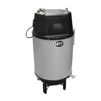
1. Choosing the correct ow paddle.
The boiler comes with a ow switch and four ow paddles. Use
the table below to determine which paddle to use with the boiler.
VWH Model Paddle Size
220 H1
299 / 301 H2
399 H3
N/A H4
Table 4 - Flow Paddle Sizing
2. Use a Phillips Head screwdriver to attach ow paddle as
shown below.
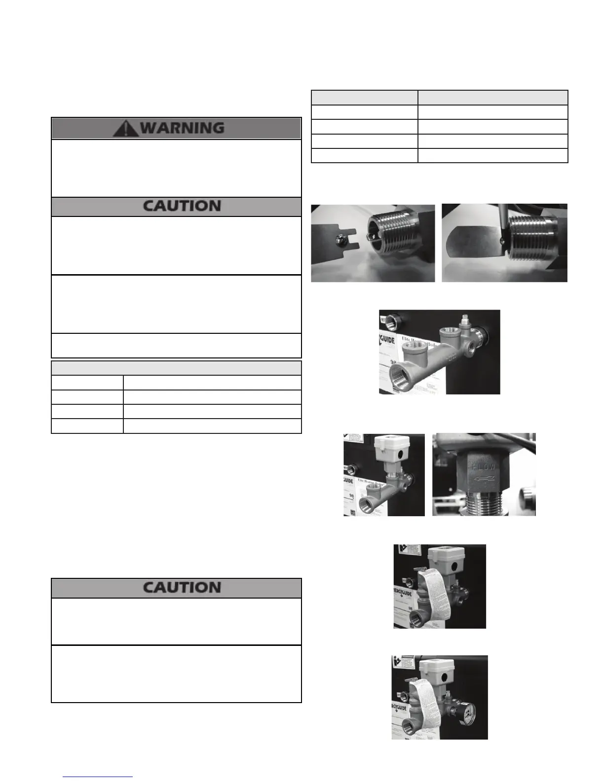
3. Thread outlet combination tting onto supply outlet of boiler
using pipe dope.
4. Thread ow switch into outlet combination tting using pipe
dope, making certain the FLOW arrow points in the correct
direction.
5. Thread relief valve into outlet combination tting using pipe
dope.
6. Thread temperature and pressure gauge into outlet
combination tting using pipe dope.
 Loading...