LP-551 Rev. 3.9.16
25
Description Stock Code
3” PVC Concentric Termination Kit KGAVT0601CVT
3” Stainless Steel Termination Kit V1000
4” Stainless Steel Termination Kit V2000
6” Stainless Steel Termination Kit V3000
3” Polypro Vent Kit 8400P-001
Table 16 - Optional Vent Kits
not be the preferred venting option. To save time and cost,
carefully consider venting installation and location.
10. Horizontal lengths of exhaust vent must slope back towards
the boiler not less than ¼” per foot to allow condensate to
drain from the vent pipe.
11. The exhaust vent must terminate where vapors cannot
make accidental contact with people or pets, or damage
shrubs or plants.
12. In vacant chimney applications, install and seal a rain cap
over existing chimney openings.
13. All piping must be fully supported. Use pipe hangers at a
minimum of 4 foot intervals to prevent sagging of the pipe
where condensate may form.
14. Do not use the boiler to support any piping.
15. Ensure the outdoor exhaust vent termination is screened
to prevent blockage caused by debris or birds.
16. Ensure the outdoor intake pipe termination is screened to
prevent blockage caused by debris or birds.
The following table lists optional exhaust/intake terminations
available from HTP:
H. Applications
1. Direct Vent Installation of Exhaust and Intake
If installing a direct vent option, combustion air must be
drawn from the outdoors directly into the boiler intake, and
exhaust must terminate outside. There are three basic direct
vent options detailed in this manual: 1. Side Wall Venting, 2.
Roof Venting, and 3. Unbalanced Venting.
Be sure to locate the boiler such that the exhaust vent and
intake pipe can be routed through the building and properly
terminated. Dierent vent terminals can be used to simplify
and eliminate multiple penetrations in the building structure
(see Optional Equipment in Venting Section). The exhaust
vent and intake pipe lengths, routing and termination
methods must all comply with the methods and limits given
in the Venting section of this manual.
When installing a combustion air intake from outdoors, care
must be taken to utilize uncontaminated combustion air.
NOTE: To prevent combustion air contamination, see Table 2.
Take extra precaution to adequately support the weight of
vent pipes terminating through the roof. Failure to properly
support roof terminated piping could result in property
damage, serious injury, or death.
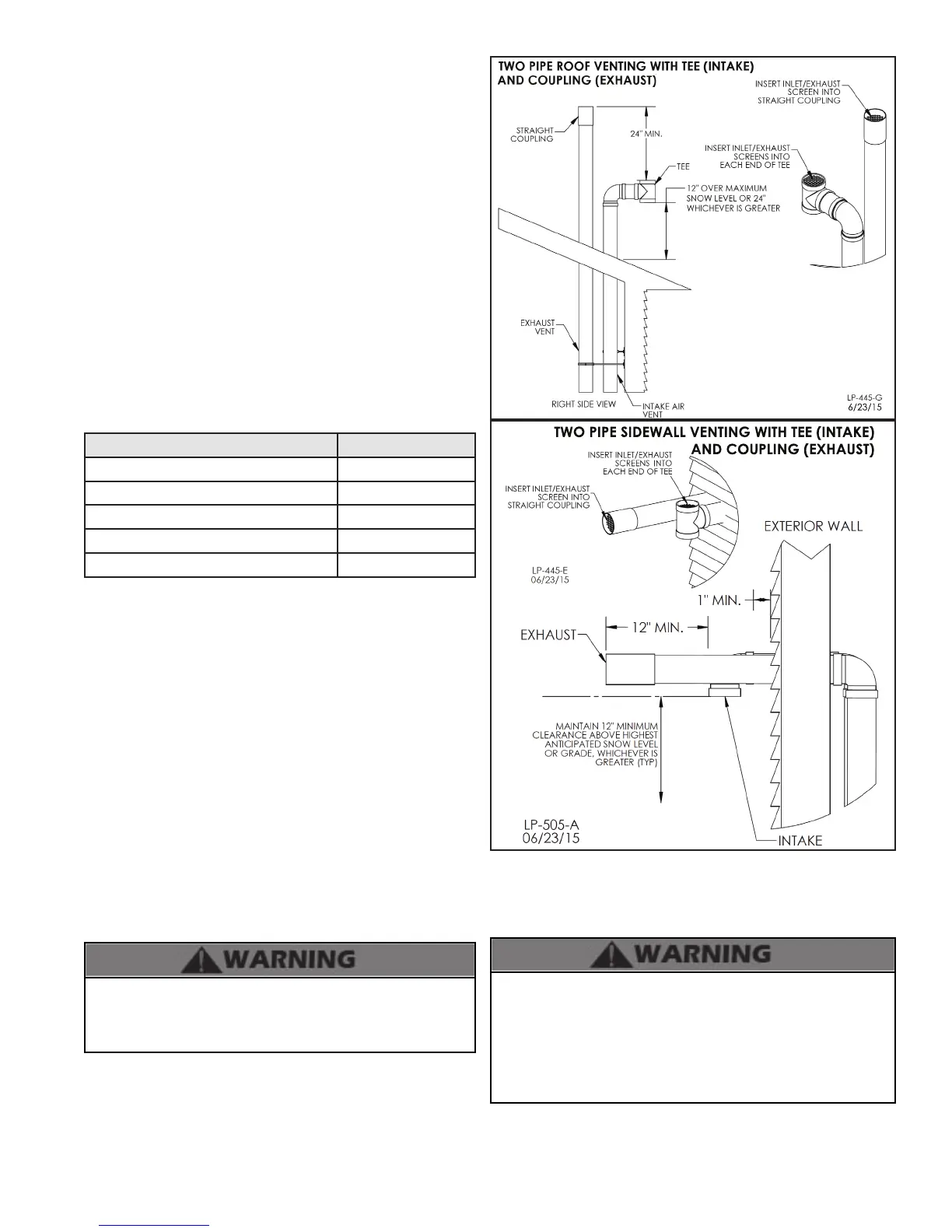
TWO PIPE SIDEWALL VENTING WITH TEE (INTAKE)
AND COUPLING (EXHAUST)
Figure 13 - Two Pipe Roof and Sidewall Venting
NOTE: These drawings are meant to demonstrate system
venting only. The installer is responsible for all equipment and
detailing required by local codes.
All vent pipes must be glued, properly supported, and the
exhaust pitched a minimum of 1/4” per foot back to the boiler to
allow drainage of condensate. When placing support brackets
on vent piping, the rst bracket must be within 1 foot of the
boiler and the balance of 4 foot intervals on the vent pipe.
Venting must be readily accessible for visual inspection from
the rst three feet from the boiler.

 Loading...