LP-551 Rev. 3.9.16
30
The condensate line must remain unobstructed. If allowed to
freeze in the line or obstructed in any other manner, condensate
can exit from the boiler tee, resulting in potential water damage
to property. When installing a condensate pump, select one
approved for use with condensing boilers and furnaces. The
condensate pump should have an overow switch to prevent
property damage from spillage. Condensate from the boiler will
be slightly acidic (pH from 3.2 to 4.5). Install a neutralizing lter
if required by local codes.
Power to the optional condensate pump is continuous. When
the boiler is powered o the condensate pump will remain on.
It is important to remember to turn o the condensate pump
when powering down the boiler. Failure to do so could result in
property damage, severe personal injury, or death.
3. A frozen condensate line could result in a blocked vent
condition. It is very important to protect the condensate line from
freezing temperatures or any type of blockage. In installations
that may encounter sustained freezing conditions, the use of
heat tape is recommended to avoid freezing of the condensate
line. It is also recommended to bush up the condensate line size
to 1” and terminate condensate discharge as close to the unit as
possible. Longer condensate runs are more prone to freezing.
Damages due to frozen or blocked condensate lines ARE NOT
covered by warranty.
4. Support of the condensate line may be necessary to avoid
blockage of the condensate ow.
5. To allow proper drainage on longer horizontal condensate
runs, tubing size may need to increase to 1” and a second line
vent may be required.
NOTE: To clean out condensate trap, see Maintenance section.
Is is very important that condensate piping be no smaller than
1/2”. Use a tee at the condensate connection with a branch
vertically up and open to the atmosphere to prevent a vacuum
that could obstruct the ow of condensate from the boiler. To
prevent sagging and maintain pitch, condensate piping should
be supported with pipe supports.
When installing a condensate pump, select one approved for
use with condensing boilers and furnaces. The pump should
have an overow switch to prevent property damage from
condensate spillage.
Part 6 - Wiring
To avoid electrical shock, turn o all power to the boiler prior
to opening an electrical box within the unit. Ensure the power
remains o while any wiring connections are being made.
Failure to follow these instructions could result in component or
product failure, serious injury, or death. Such product failure IS
NOT covered by warranty.
Jumping out control circuits or components WILL VOID product
warranty and can result in property damage, personal injury, or
death.
Label all wires prior to disconnecting them when servicing
the boiler. Wiring errors can cause improper and dangerous
operation. Failure to follow these instructions may result in
property damage or personal injury.
It is of extreme importance that this unit be properly
grounded. It is very important that the building system
ground is inspected by a qualied electrician prior to making
this connection. Electrical power must only be turned on
when the boiler is completely lled with cold water. Failure
to follow these instructions could result in component or
product failure, serious injury, or death.
Electrical Shock Hazard - Turn o electrical power supply
at service entrance panel before making any electrical
connections. Failure to follow do do so could result in serious
injury, or death.
Wiring must be NEC Class 1. If original wiring supplied with
the boiler must be replaced, use only TEW 105
o
C wire or
equivalent. Boiler must be electrically grounded as required
by the National Electrical Code, ANSI/NFPA 70 - Latest
Edition.
A. Installation Must Comply With
1. National Electrical Code and any other national, state,
provincial, or local codes or regulations.
2. In Canada, CSA C22.1, Canadian Electrical Code Part 1, and
any local codes.
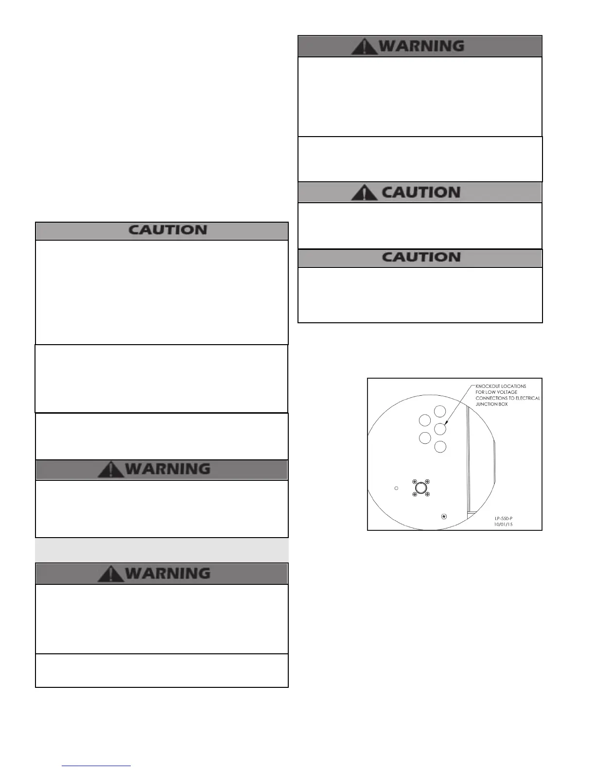
B. Field Wiring
Terminations
All connections
made to the
boiler in the eld
are done inside
the electrical
junction box
located on the
left side of the
unit. Multiple
knockout
locations are
available to route
eld wires into and out of the electrical junction box.
Figure 21 - Knockout Locations
C. Field Wiring
The control used in the boiler is capable of directly controlling
1 pump in standard mode and 2 pumps when congured as
a cascade master boiler. As a standard unit, each pump can
provide a maximum of 3 amps at 120 volts. If a pump requires
more than this amount of power, an external contactor or
motor starter is needed. If the boiler is congured as a cascade
master, the system pump output is a dry contact output
capable of switching 5 amps at 120 volts, in addition to the
boiler pump output sourcing 4 amps each.
The electrical junction box has separate, clearly marked
terminal strips for line voltage and low voltage wiring. Special
jacks are provided for trouble-free cascade system wiring
using standard CAT3 or CAT5 patch cables.

 Loading...