LP-551 Rev. 3.9.16
39
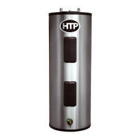
E. Setting Up a Single Boiler
When power is applied to the boiler, the control rst
completes a power-up systems check. During this time the
combustion fan may run. The display will initially show the
current boiler outlet temperature. If a fault is detected during
the power-up test, the control will display the appropriate
fault code. Otherwise, the display will continue to show the
boiler outlet temperature and stand-by, waiting for a demand
for hot water. If the temperature of the tank sensor falls below
the tank set point minus the tank dierential temperature, a
demand for hot water is generated by the control.
When a demand for hot water is received, the control begins
the following demand sequence. The boiler rst turns on the
pump (if it is not wired to run continuously). Once the pump is
running, the control will display LOW WATER FLOW and wait
for the water ow in the system to increase to an acceptable
level determined by the ow switch on the outside of the
boiler. (NOTE: This step may happen very rapidly. If ow is
adequate, LOW WATER FLOW may never display.)
Once ow through the boiler is adequate, the control will
measure the supply temperature. If it is below the set point
temperature minus the ignition dierential set point, the
control will ignite the burner. After the burner is lit, the
control modulates the ring rate to control the supply water
temperature at the set point temperature plus the supply
oset temperature (installer #4) above the tank set point
temperature. When the tank temperature is equal to the
tank set point temperature, the control will extinguish the
burner and run the combustion fan to purge gasses from the
combustion chamber. In addition, the pump will run for a
pump post purge interval. The control will then be in standby,
waiting to process the next demand for heat.
During this process, the control will extinguish the burner
if it senses a dangerous or unsafe condition. If the control
determines that a dangerous or unsafe condition has occurred,
the control may lock out the boiler and prevent it from igniting
until a maintenance person diagnoses the problem, repairs
it, and resets the control. In the event that the control goes
into lockout, it will show a diagnostic code on the display,
illuminate the LED fault indicator, and close the alarm relay
contacts to aid in recognition of the condition, diagnosis, and
repair.
F. Setting Up a Cascaded System
If the boiler is part of a cascaded system the operation is
somewhat dierent. The control of each boiler in a cascaded
system completes its own power up system check as described
above. One of the boilers in the cascade system is designated
as the master boiler. After the master boiler completes its
power up sequence, it checks the communication bus to see if
any other boilers are present. If other boilers are present, the
master control determines these follower boiler addresses.
The master boiler control will recheck the bus every few
seconds as long as it is powered up to update the status of the
connected boilers. The control in the master boiler processes
all heat demands and dictates which of the follower boilers
should light and what ring rate the followers should try to
achieve.
When the master boiler receives a demand for heat, it
determines which boiler is rst in the ring sequence and
sends that boiler a command to begin a demand sequence. That
boiler will then begin a demand sequence as described above.
Once the boiler ignites, the master boiler control will increase
the ring rate command to that boiler until the system sensor
temperature is at the tank set point temperature plus the supply
oset temperature (installer #4), or that boiler is at high ring
rate. If the command from the master boiler control gets to the
high ring rate of the follower boiler, but the system sensor is
below the required temperature, the master boiler control
will then tell the next boiler in the ring sequence to begin its
demand sequence. The master boiler control will then begin to
ramp up the ring rate command of that boiler. This process will
continue while there is a demand until all boilers in the cascade
system are at high re or the desired temperature of the system
sensor is reached. If the system sensor temperature reaches
tank set point and installer #4 before all boilers are at high re,
the master control will modulate the cascade command signal
to maintain the system sensor at tank set point and installer
#4 until the demand is complete. When the tank temperature
is equal to the set point temperature, the demand is complete,
and the master boiler control will extinguish all boilers that may
be lit. If the demand decreases, the ring rate command and
amount of boilers lit will decrease exactly opposite as described
above.
Whenever the master boiler control needs to re a follower
boiler, it sends a ring rate command to that boiler. The
follower boiler will respond to the command until its supply
sensor temperature gets to be 5
o
F above the tank set point
temperature plus the supply oset temperature (installer #4),
at which point the individual boiler will modulate on its own so
as not to overheat. As a result, it is not uncommon to see the
cascade output at maximum but individual boilers ring at less
than their maximum ring rate.
G. Lockout Condition
If any boilers, including the master boiler in the cascade system,
are in a lockout condition, the master control will recognize the
lockout condition and skip over the boiler in the ring sequence.
Each boiler in the cascade system is responsible for its own
safety functions. So, if any individual boiler control senses an
unsafe condition, it will extinguish the burner and, if necessary,
go to a lockout condition. In this way, every boiler in the system
has its individual safety controls intact and operational, even if
the ring of the boiler is under control of the master boiler.
In the event that the system sensor fails, all boilers in the
system will ignite simultaneously when there is a demand, and
each boiler will individually regulate ring rates to maintain
the master set point temperature (tank set point + installer
#4) at the individual supply sensors built into the boiler. If this
should happen, the master boiler will display an E03 fault code,
indicating that the supply sensor has failed.
H. Cascade System Programming
1. If the boiler is used alone, skip this section.
2. Programming the Master Boiler:
a. Make sure there is no demand for heat being supplied to
the boiler.
b. Apply power to the boiler.
c. Enter the system setting program navigation following
instructions in Part 10 of this manual.
d. Verify that cascade address function 15 is set to 0. This

 Loading...