LP-551 Rev. 3.9.16
17
Heat Exchanger Pressure Drop
Flow Rate in GPM and Corresponding Pressure Drop in Feet (Δ P’)
Model 6 7 8 9 10 11 12 13 14 15 16 17 18 19 20 21 22
220 * * * * * * * * * 8’ 10’ 11.5’ 13’ 15’ 16.5’ 17’ 19’
299 / 301 * * * * * * * * * * * * * * 13’ 14’ 15’
399 * * * * * * * * * * * * * * * * *
Model 23 24 25 26 27 28 29 30 31 32 33 34 35 36 37 38 39
220 21’ 23’ 24’ * * * * * * * * * * * * * *
299 / 301 16.5’ 18’ 20’ 22’ 24’ 26’ 29’ 33’ 36’ * * * * * * * *
399 * * * 12.9’ 13.6’ 14’ 15.7’ 17’ 18’ 19.4’ 21’ 22.5’ 26’ 28’ 31’ 34’ 39’
Table 8 - *Do not operate the boiler at these ow rates. These low or high ow rates will damage the heat exchanger or related
components. Damages due to improper operation ARE NOT covered by warranty.
The chart below represents various system design temperature rise through the boiler along with respective ows and friction
loss. This is provided to aid in circulator selection.
System Temperature Rise Chart
20°Δt 25°Δt 30°Δt
Model Friction Ft Flow Rate (GPM) Friction Ft Flow Rate (GPM) Friction Ft Flow Rate (GPM)
220 19’ 22 13’ 18.3 12’ 14.6
299 / 301 29’ 29 18’ 24.5
13’
20
399 39’ 39 19’ 32.5 26
Table 9 - Temperature Rise, Friction Ft and Flow Rate
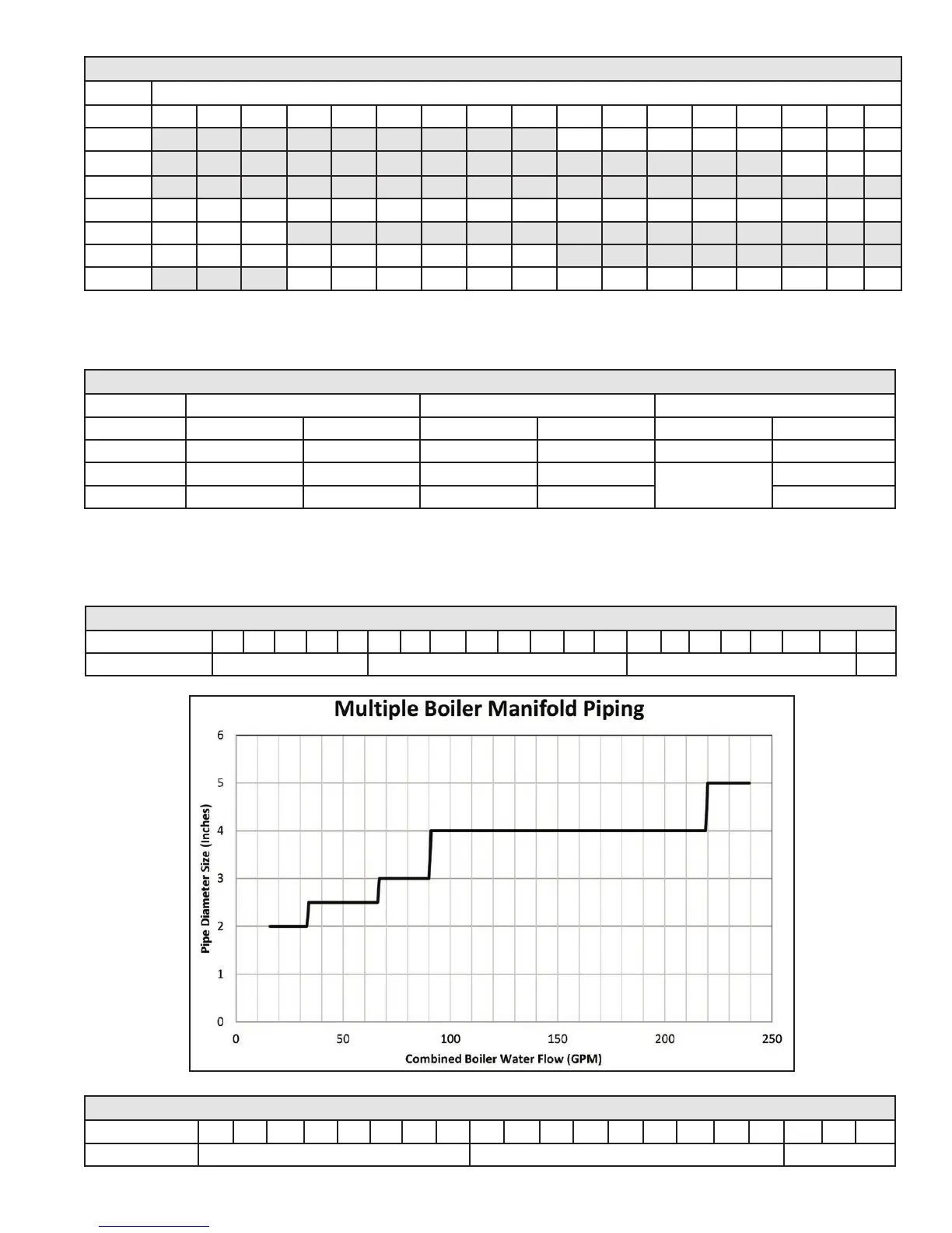
The chart below represents the combined ow rates and pipe sizes when using multiple boilers to design the manifold system for
the primary circuit. To size, simply add up the number of boilers and the required ow rates for the system design temperature.
Example: (5) 220 model boilers with a design of 20°Δt degree temperature rise with each boiler having an individual ow rate of
22 GPM. To correctly size the manifold feeding these (5) boilers you would need a pipe size of 4”.
Multiple Boiler Manifold Piping
Flow Rate (GPM) 16 22 24 30 32 33 40 44 45 48 50 55 60 66 75 80 85 88 90 100 110
Pipe Dia. (In.) 2 2 1/2 3 4
Table 10 - Multiple Boiler Manifold Piping
Figure 6 - Multiple Boiler Manifold Piping
Multiple Boiler Manifold Piping
Flow Rate (GPM) 120 132 150 160 170 179 200 210 239 240 250 255 300 340 350 400 425 510 595 680
Pipe Dia. (In.) 4 5 6
Table 11 - Multiple Boiler Manifold Piping

 Loading...