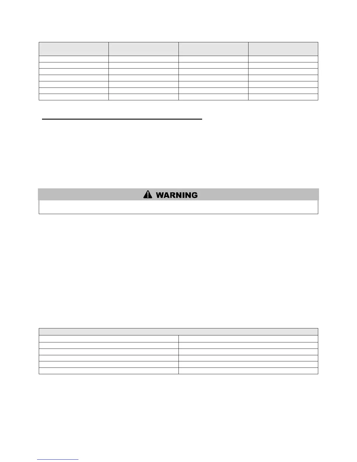
40
Transition Point (ft
from water heater)
TEL of Standard 2”
Vent Pipe (ft)
TEL of Oversized 2”,
3”, or 4” Vent Pipe (ft)
Maximum TEL of all
Vent Pipe (ft)
Table 9 – TEL = Total Equivalent Length
F. EXHAUST AND INTAKE AIR VENT INSTALLATION
1. Use only solid PVC or CPVC pipe. FOAM CORE PIPING IS NOT APPROVED. Refer to Table 6 for
approved materials.
2. Remove all burrs and debris from joints and fittings.
3. All joints must be properly cleaned, primed, and cemented. Use only cement and primer approved for
use with the pipe material. Cement must conform to ASTM D2564 for PVC and ASTM F493 for CPVC
pipe.
All joints of positive pressure vent systems must be sealed completely to prevent leakage of flue products
into the living space.
4. Horizontal lengths of exhaust vent must slope towards the water heater not less than ¼” per ft to allow
condensate to drain from the vent pipe. If the exhaust pipe must be piped around an obstacle that results
in the creation of a low point, condensate will collect and form a blockage. This condensate must be
drained away using a field-installed condensate drain assembly (see Figure 26).
5. All piping must be fully supported. Use pipe hangers at a minimum of 4 ft intervals to prevent sagging
of the pipe where condensate may form.
6. Do not use the unit to support any piping.
7. A screened straight coupling is provided with the unit for use as an outside exhaust termination.
8. A screened inlet air tee is provided with the water heater to be used as an outside intake termination.
9. The following table lists optional intake air/exhaust vent terminations available from HTP.
2” PVC Concentric Vent Termination Kit
3” PVC Concentric Vent Termination Kit
2” Stainless Steel Vent Termination Kit
3” Stainless Steel Vent Termination Kit
4” Stainless Steel Vent Termination Kit
Table 10