2
Note:
Figures of the front panel and the rear panel are only for your
reference.
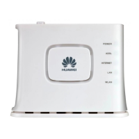
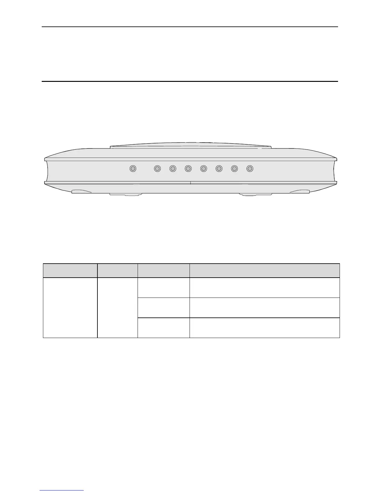
1.2.1 Front Panel
Figure 1-1 shows the front panel of the HG520s.
WLAN
LAN4 LAN3 LAN2 LAN1 INTERNET ADSL POWER
Figure 1-1 Front panel of the HG520s
Table 1-1 shows indicators in the front panel.
Table 1-1 Indicators in the front panel
Indicator Color Status Description
On
The connection is established in the
WLAN interface.
Blinking
There are data being transmitted in
the WLAN interface.
WLAN Green
Off
No connection is established in the
WLAN interface.
 Loading...