(Optional) Connecting the Teamwork Network Cable
9.4
19
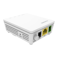
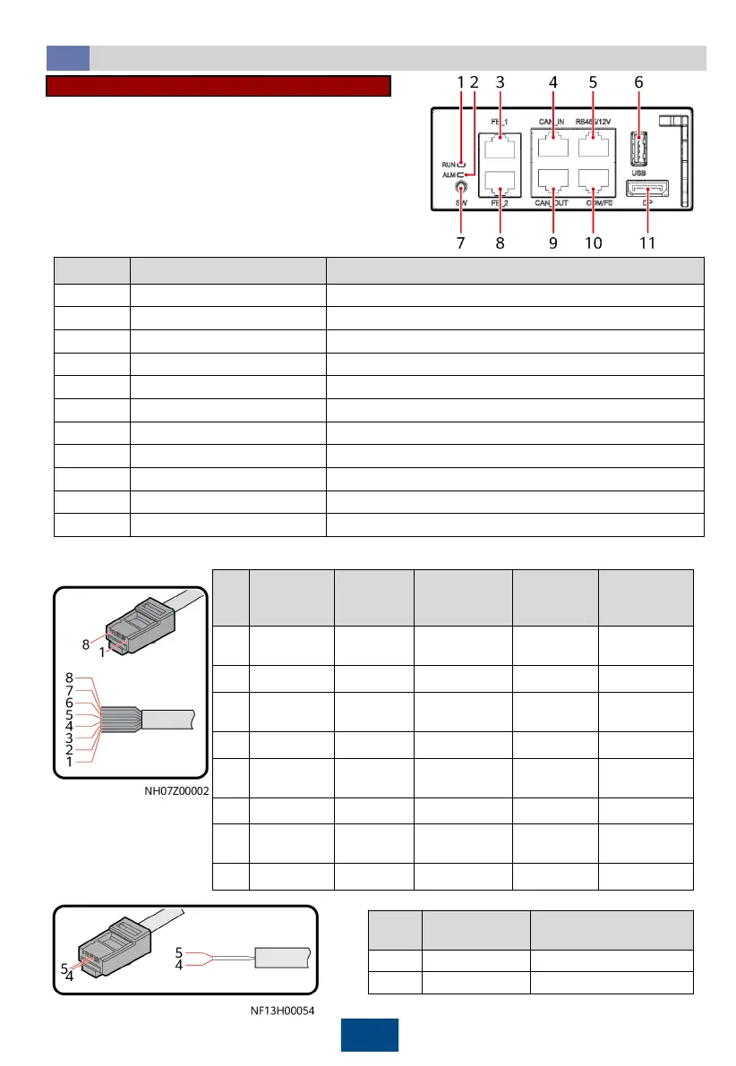
Ports on the Main Control Module
No. Name Description
1
Running indicator
-
2
Alarm indicator
-
3 FE_1 port FE teamwork control
4 CAN_IN port CAN teamwork and RS485 monitoring cascading
5 RS485/12V port Connecting to a T/H sensor
6 USB port Connecting to a WiFi module or USB flash drive
7 SW button
Button for restoring factory settings
8 FE_2 port FE teamwork control
9 CAN_OUT port CAN teamwork and RS485 monitoring cascading
10 COM/FE port Connecting to a monitoring communications cable
11 DP port Connecting to the display
a) Prepare network cables.
PIN Color
FE_1 and
FE_2
CAN_IN and
CAN_OUT
RS485/12V
Port
COM/FE
(FE
Monitoring)
1
White-and-
orange
FE TX+
RS485 T+ (+) RS485 HT+ FE TX+
2 Orange
FE TX–
RS485 T– (–) RS485 HT– FE TX–
3
White-and-
green
FE RX+
- 12V FE RX+
4 Blue
-
RS485 R+ RS485 HT+ RS485+
5
White-and-
blue
-
RS485 R– RS485 HT– RS485–
6 Green
FE RX–
- - FE RX–
7
White-and-
brown
-
CANH - -
8 Brown
-
CANL GND -
PIN Color
COM/FE Port (RS485
Monitoring)
4 Blue RS485+
5 White-and-blue RS485–
 Loading...