UPS5000-E-(50 kVA-300 kVA)
User Manual (50 kVA Power Modules)
Huawei Proprietary and Confidential
Copyright © Huawei Technologies Co., Ltd.
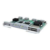
Figure 2-18 Monitoring interface card
Table 2-5 describes the ports on the monitoring interface card.
DO_1 to DO_4 meet the maximum voltage and current requirements of 30 V DC/1 A or 60 V DC/0.5 A.
Table 2-5 Ports on the monitoring interface card
DO_1 is used to output alarms and indicates critical alarms by
default. It can be set to indicate minor alarms, bypass mode,
battery mode, or low battery voltage.
DO_2 is used to output alarms and indicates minor alarms by
default. It can be set to indicate critical alarms, bypass mode,
battery mode, or low battery voltage.
DO_3 is used to output alarms and indicates bypass mode by
default. It can be set to indicate critical alarms, minor alarms,
battery mode, or low battery voltage.
DO_4 is used to output alarms and indicates battery mode by
default. It can be set to indicate critical alarms, minor alarms,
bypass mode, or low battery voltage.
Provides FE, RS485, I2C, and CAN signals.
Battery
temper
ature
sensor
port
Connects to an indoor battery temperature sensor.
Southb
ound
commu
nicatio
ns port
1
Connects to an ambient temperature and humidity sensor over two
wires.
Connects to a southbound device, such as an iBAT 2.0.

 Loading...


