Do you have a question about the Huber 705 and is the answer not in the manual?
Covers safety instructions, symbols, proper operation, and misuse.
Details obligations for responsible bodies and operators.
Provides guidelines for safely transporting the unit within the facility.
Describes the function and handling of transportation locks.
Details the necessary conditions for installing the temperature control unit.
Covers special considerations for outdoor installation and winter operation.
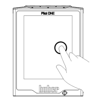
Details steps required before operating the unit.
Guides on connecting external applications, closed and open.
Details how to connect the unit to the power supply.
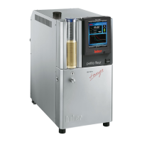
Describes the general and specific functions of the temperature control unit.
Covers compatibility, properties, and handling of thermal fluids.
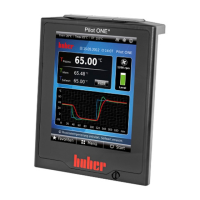
Explains the internal temperature control circuit and its parameters.
Details procedures for filling, venting, degassing, and draining the unit.
Covers routine maintenance tasks for the unit.
Covers inspection, replacement, and cleaning of the thermal fluid circuit.
Highlights critical safety instructions for shutting down the unit.
| Heating Power | 2 kW |
|---|---|
| Input Type | Pt100 |
| Control Algorithm | PID |
| Power Supply | 230 V / 50 Hz |
| Operating Temperature | 5°C to 40°C |
| Cooling Power at 20°C | 700 W |
| Bath Volume | 7 L |