Commissioning
OPERATION MANUAL Chapter 2
Unistat® V2.0.0en/09.06.16//15.09
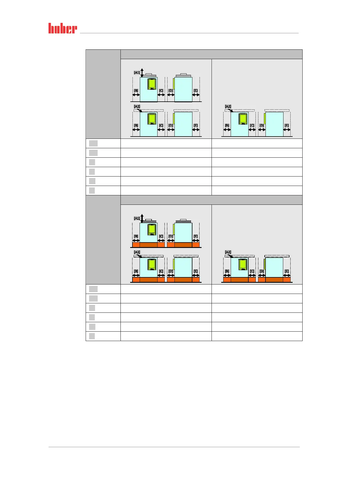
Side of the
temperature
control unit
Clearance to the temperature control unit in cm
Air cooling
Water cooling
[A1] Top Air outlet on top of unit: free standing –
[A2] Top can be located under a bench can be located under a bench
[B] Left min. 20 min. 10
[C] Right min. 20 min. 10
[D] Front min. 20 min. 10
[E] Rear min. 20 min. 20
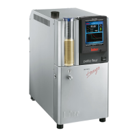
Side of the
temperature
control unit
Clearance to the temperature control unit in cm (for operation in a bath)
Air cooling
Water cooling
[A1] Top Air outlet on top of unit: free standing –
[A2] Top can be located under a bench can be located under a bench
[B] Left min. 20 min. 20
[C] Right min. 20 min. 20
[D] Front min. 20 min. 20
[E] Rear min. 20 min. 20
2.4.1 EMC-specific notes
▪ Class A Group 1 equipment according to IEC_EN CiSPR 55011 is intended to be used in “industrial
electromagnetic environments”. Their electromagnetic compatibility may be affected if operated
in other electromagnetic environments.
▪ Class B equipment according to IEC_EN CiSPR 55011 is suitable for use in “basic electromagnetic
environments”.
▪ The temperature control unit has the immunity required by EN 61326-1 for the operation in “in-
dustrial electromagnetic environments”.
▪ See the data sheet from page 96 in section »Annex« for the classification of your temperature
control unit.
▪ For more information on electromagnetic compatibility see www.huber-online.com.
Wall clearance to
temperature control
unit