Commissioning
OPERATION MANUAL Chapter 2
Unistat® V2.0.0en/09.06.16//15.09
2.11 Connecting an externally closed/open application
The illustration “connection diagram” can be found on page 96 in section »Annex«.
2.11.1 Connecting an externally closed application
Operating an externally closed system with >Isolating sleeve< [27] installed
BURSTING DUE TO OVERPRESSURE DURING TEMPERATURE CONTROL.
Shut down the temperature control unit immediately.
Allow the thermal fluid to cool to room temperature.
Prior to starting up the temperature control unit with an externally closed system, remove the >Iso-
lating sleeve< [27] (see page 33, in section »Mounting/removing the isolating sleeve (optional)«).
In case of standard devices, open the >Venting valve expansion vessel< [21] by turning it anti-
clockwise (turn 90° left as far as it will go).
Pressure > 0.5 bar (g) with glass apparatus
MATERIAL DAMAGE CAUSED BY CRACK FORMATION AT THE GLASS APPARATUS.
Provide an over-pressure protective device to prevent damage to the glass apparatus.
Do not install valves/quick-release couplings in the feed/discharge lines from the temperature con-
trol unit to the glass apparatus and from the glass apparatus to the temperature control unit.
If valves/quick-release couplings are required:
Install burst disks on the glass apparatus itself (at the feed and discharge lines).
Install a bypass upstream of the valves/quick-release couplings for the glass apparatus.
Matching accessories (e.g. bypasses to reduce pressure) can be found in the Huber catalog.
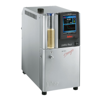
To enable your application to be operated correctly and eliminate air bubbles from the system, you
must ensure that the >Circulation flow< [1] connection from the temperature control unit is at-
tached to the lower connection point of the application and the >Circulation return< [2] into the
temperature control unit is attached to the higher connection point of the application.
PROCEDURE
Remove the screw plugs from the >Circulation flow< [1] and >Circulation return< [2] connections.
Then connect your application to the temperature control unit using suitable thermal fluid hoses.
The corresponding wrench sizes can be found in the table on page 30 in section »Wrench sizes
and torques«.
Check the connections for leaks.
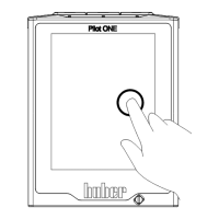
2.11.2 Connecting an externally open application (bath)
Operating an externally open system without >Isolating sleeve< [27] installed
BURNS/FREEZING DUE TO OVERFLOWING EXPANSION VESSEL
Prior to starting up the temperature control unit with an externally open system, install the >Isolat-
ing sleeve< [27] (see page 33 in section »Mounting/removing the isolating sleeve (optional)«).
Close the >Venting valve expansion vessel< [21] for all stand-alone units by turning them
clockwise (turn 90° right as far as it will go).
Example: Connecting
an externally closed
application
Example: Connecting
an externally open
application