Interfaces and software update
OPERATION MANUAL Chapter 6
Unistat® V2.0.0en/09.06.16//15.09
▪ “Unipump with Echo”: This function is used to check whether the Unipump controlled by the
POKO runs synchronous with the Unistat pump. For this purpose, the operating mode of the
Unipump is applied via a make contact to the “LEVEL” socket. A fault is generated if asynchro-
nous. This mode is useful if a Unipump is to be monitored - either to guarantee the desired circu-
lation or to prevent an unintended heating of the thermal fluid.
▪ “Programmer”: This activates the individual segments associated during program creation with
the POKO switching states.
▪ “Internal temperature absolute”: This enables you to set a temperature range relative to the
internal sensor (absolute temperature). The POCO is active outside of this range; the POCO is in-
active inside of this range.
▪ “Process temperature absolute”: This enables you to set a temperature range relative to the
process temperature (absolute temperature). The POCO is active outside of this range; the POCO
is inactive inside of this range.
▪ “Solenoid valve flow / return flow”: This function is used to control a connected solenoid valve. It
takes 60 seconds before the POKO switches on after you have started the pump in the tempera-
ture control unit. For example, the POKO is switched off before the pump has been completely
stopped when the temperature control process / circulation is stopped. Thus, the POKO is
switched on only as long as the full pump pressure exists.
▪ “Cooling”: This function is used to open the cooling water supply with a solenoid valve only when
the temperature control unit requires cooling water. The POKO is switched on when the tempera-
ture control unit is cooling.
With the floating contact, use only sheathed lines! The interface is specified as a digital output.
The connection is designed as a potential-free changeover contact.
Closing contact between pin 1 and pin 2.
Opening contact between pin 2 and pin 3.
Contact load: 1 A at 24 V DC.
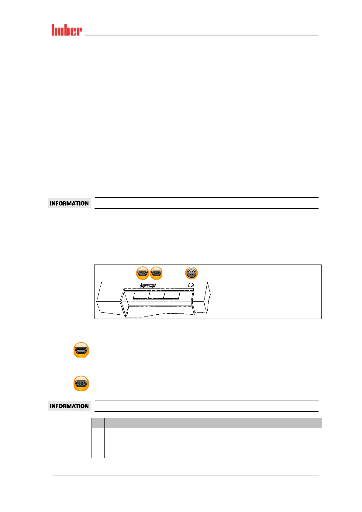
6.2.2 Interfaces at the “Unistat® Control ONE” top side
6.2.2.1 Service interface
This interface is used by the service engineers of Peter Huber Kältemaschinenbau AG exclusively for
service purposes. An adapter cable connects this interface to a RS232 serial jack.
6.2.2.2 Female RS232 Serial (with adapter cable)
A PC, a SPS or a Process Control System (PCS) can be connected to this jack for remote control of the
controller electronics. Before plugging in the cable, check the settings in the “Interfaces” category
and adjust if necessary.
The interfaces used must meet the specifications of the generally accepted standards.
Pin Signal Description
2 RxD Receive Data
3 TxD Transmit Data
5 GND Signal GND
Standard interfaces
at the “Unistat Con-
trol ONE” top side.
Pin assignment