Setup mode
OPERATION MANUAL Chapter 4
Unistat® V2.0.0en/09.06.16//15.09
The volume expansion of the thermofluid depends on the working temperature range you wish to
work in. A “Min” mark must not be undercut in the bath vessel (top edge of the back flow + ca. 1
cm safety) at the “lowest” working temperature and a “Max” mark must not be exceeded in the
bath vessel at the “highest” working temperature. In the event of overfilling a table-top model and
prior to starting, drain thermofluid into a suitable container via >Drain< [8] by additionally opening
the >Drain valve thermofluid< [3] (by turning it counterclockwise (turn it 90° to the left as far as it
will go)) or by skimming off bath liquid from the bath. In case of free-standing models, drain ther-
mofluid via >Drain< [8] and by opening the >Drain valve thermofluid< [3] (by turning it counter-
clockwise (turn 90° to the left as far as it will go)). Check if the thermofluid can be reused. On page
16 observe section »Proper disposal of resources and consumables«. In case of too little ther-
mofluid, the pump sucks air instead of thermofluid. This “dry run” of the pump is detected by the
sensors and the electronics and a safety shutdown occurs. Therefore, please provide for sufficient
thermofluid.
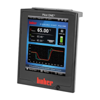
Stop venting. To do this, go to the category “Temperature Control”.
Tap on the category “Start/Stop”.
Tap on the dialog entry “Stop air-purge”.
Confirm your choice by tapping on “OK”. Venting is stopped and the pump continues to run for
approx. 30 seconds. Wait until the pump stops.
4.3.2.2 Degassing externally open applications
Hot or cold thermal fluid and surfaces
BURNS TO LIMBS
Avoid direct contact with the thermal fluids or the surfaces.
Wear your personnel protective equipment (e.g. temperature-resistant safety gloves, safety
goggles, safety footwear).
When changing from low-boiling thermal fluid (low-boiling component) to higher boiling thermal
fluid, remains of the low-boiling component may remain in the temperature control unit. Depend-
ing on the working temperature, the low-boiling component begins to boil, gas bubbles form and
cause the pump pressure to momentarily collapse. This may cause a safety shutdown. The gas
bubbles reach the bath opening and can escape.
If ice crystals form on the evaporator coil, water has accumulated in the thermal fluid. If this is the
case, degas to avoid damage to the temperature control unit.
Thermal fluids are hygroscopic (water-attracting) to a greater or lesser degree. This effect increases
as the working temperature decreases. The off-gassing mode below, which must be permanently
monitored, also helps you remove any water residues from the temperature control circuit.
PROCEDURE
Follow venting with the degassing operation. Prerequisite: You have filled the temperature con-
trol unit according to the instructions on page 69 in Section »Filling and venting externally open
application« and/or cleaned it as per page 88 in Section »Rinsing the thermal fluid circuit«.
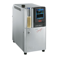
Go to the “Home” screen.
Tap on the keypad symbol next to “T
Setpoint
”.
Enter a setpoint using the number keypad that appears. This setpoint must be below the low-
boiling thermofluid. This setpoint will be increased in 10 K steps during the degassing process up
to the maximum working temperature.
Confirm your entry by tapping on “OK”.
In the display that follows, confirm your entry again by tapping on “OK”.
The correct selection will be displayed graphically and the setpoint will be changed immediately.
If tapping on “OK” is not correct, it will be displayed graphically for 2 seconds. The display will re-
turn to the “Home” screen. Try changing the setpoint again.
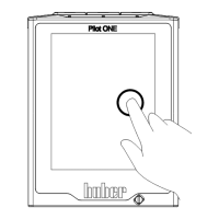
Tap on the “Start” touch button.
Confirm the start of temperature control by tapping on “OK”.
The correct selection will be displayed graphically and temperature control will start immediate-
ly. If tapping on “OK” is not correct, it will be displayed graphically for 2 seconds. The display will
return to the “Home” screen. Try starting the thermoregulation again.
Carry out temperature control to the entered setpoint until no more gas bubbles rise up.
Increase the setpoint by 10 K and carry out temperature control until no more gas bubbles rise
up.