OPERATION MANUAL
V2.0.0en/09.06.16//15.09 Unistat®
2.9 Temperature control units with water cooling .............................................. 31
2.10 Preparations for operation ........................................................................... 32
2.10.1 Unscrewing/activating the leveling feet (if any) ............................................. 32
2.10.2 Opening/closing valves ................................................................................... 32
2.10.3 Mounting/removing the isolating sleeve (optional) ....................................... 33
2.10.3.1 Mounting the Isolating sleeve (only for externally open applications) ...... 33
2.10.3.2 Removing the Isolating sleeve (only for externally closed applications) .... 33
2.11 Connecting an externally closed/open application ........................................ 34
2.11.1 Connecting an externally closed application .................................................. 34
2.11.2 Connecting an externally open application (bath) .......................................... 34
2.12 Connecting to the power supply ................................................................... 35
2.12.1 Connection using socket with protective earth (PE) ....................................... 35
2.12.2 Connection via hard wiring ............................................................................. 35
2.12.3 Connecting the functional earth ..................................................................... 36
2.12.4 Converting the power supply connection ....................................................... 36
3 Function description 37
3.1 Function description of the temperature control unit ................................... 37
3.1.1 General functions ............................................................................................ 37
3.1.2 Other functions ............................................................................................... 37
3.2 Information on the thermal fluids ................................................................ 38
3.3 To be noted when planning the test ............................................................. 39
3.4 “Pilot ONE®” controller ................................................................................ 40
3.4.1 Functional overview of “Pilot ONE®” .............................................................. 40
3.5 Unistat® LED diagram ................................................................................... 42
3.6 Clock/event function .................................................................................... 42
3.6.1 Rechargeable accumulator ............................................................................. 42
3.6.2 Programmable event function ........................................................................ 43
3.6.2.1 Event function “Alarm clock event” ........................................................... 43
3.6.2.2 Event function “Program event” ................................................................ 43
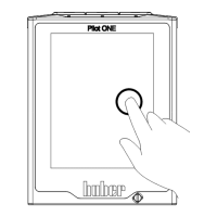
3.7 Operation via the touch screen ..................................................................... 43
3.8 Display instruments ..................................................................................... 43
3.8.1 The touchscreen [88] ...................................................................................... 43
3.8.2 The LED-Indicator Temperature [90] .............................................................. 44
3.8.3 The LED-Indicator Flow Chart [91] .................................................................. 44
3.8.4 The LED-Indicator Status [92] ......................................................................... 44
3.9 Control instruments ..................................................................................... 44
3.9.1 The touchbuttons ............................................................................................ 44
3.9.2 The categories ................................................................................................. 44
3.9.3 The sub-categories .......................................................................................... 45
3.9.4 The dialogs ...................................................................................................... 45
3.10 Function examples ....................................................................................... 45
3.10.1 Display of software version ............................................................................. 45
3.10.2 Start & Stop ..................................................................................................... 45
3.10.3 Copying the settings to a data carrier ............................................................. 46
3.10.3.1 Saving to a USB flash drive ......................................................................... 46
3.10.3.2 Loading from a USB flash drive ................................................................... 46
3.10.4 Restore factory settings .................................................................................. 47
3.10.4.1 Restore to factory settings without overtemperature protection ............. 48
3.10.4.2 Restore to factory settings including overtemperature protection ........... 48
4 Setup mode 50
4.1 Setup mode ................................................................................................. 50