Function description
Chapter 3 OPERATION MANUAL
V2.0.0en/09.06.16//15.09 Unistat®
3.3 To be noted when planning the test
Also observe page 15 in section »Proper operation«.
The focus is on your application. Bear in mind that system performance is influenced by heat trans-
fer, temperature, thermal fluid viscosity, volume flow and the flow speed.
▪ Make sure that the electrical connection is adequately dimensioned.
▪ The installation location of the temperature control unit should be selected so as to ensure ade-
quate fresh air, even with water-cooled chillers.
▪ With pressure-sensitive applications, such as glass reactors, the maximum forward flow pressure
of the temperature control unit must be taken into account.
▪ A cross-section reduction or shut-off in the thermal fluid circulation must be avoided. Take corre-
sponding measures to limit the pressure in the system; see data sheet from page 96 in Section
»Annex« and the data sheet for your glass apparatus.
▪ With temperature control units without pressure limitation, check whether it is necessary to use
an external bypass.
▪ To prevent the danger of over-pressure in the system, the thermal fluid must always be brought
to room temperature before switching off. This will prevent damage to the temperature-control
device or the application. Any isolating valves must remain open (pressure equalization).
▪ The temperature and the dynamics of the process are determined by the flow temperature. A
differential temperature (Delta T) forms between flow temperature and process temperature.
This temperature difference may have to be limited, because Delta T might exceed limits of the
application (glass apparatus) and cause bursting. Adjust the Delta T value to your application.
▪ The thermal fluid used by you must be chosen in such a way that it not only allows the minimum
and maximum working temperature but is also suitable as regards the combustion point, boiling
point and viscosity. In addition, the thermal fluid must be compatible with all the materials in your
system.
▪ Avoid bending the temperature control and cooling water hoses (if required). Use suitable angle
pieces and lay the hose connections with a large radius. Take the minimum bending radius from
the data sheet of the temperature control hoses used.
▪ The selected hose connections must be resistant to the thermal fluid, the working temperatures
and the permitted maximum pressure.
▪ Check the hoses at regular intervals for any material fatigue (e.g. cracks, leaks).
▪ Keep the length of temperature control hoses as short as possible.
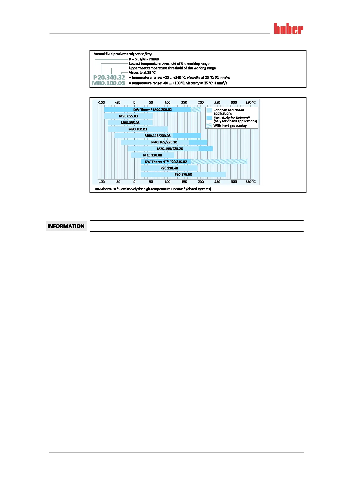
Thermal fluid product
name/product key
Overview:
Working temperature
ranges of Huber
thermal fluids