Interfaces and software update
OPERATION MANUAL Chapter 6
Unistat® V2.0.0en/09.06.16//15.09
6.1.2.1 USB-2.0 interface, host
USB-2.0 connection (for connector A), e.g. for data memories.
6.1.2.2 USB-2.0 interface, device
USB-2.0 connection (for Mini-B connector) for communicating with a computer.
6.2 Interfaces at the “Unistat® Control ONE”
6.2.1 Interfaces at the “Unistat® Control ONE” side
Connecting to the interfaces at the temperature control unit during operation
DAMAGE TO THE INTERFACES
When devices in operation are connected with interfaces of the temperature control unit,
interfaces may get damaged.
Before connecting, ensure the temperature control unit and the device to be connected are
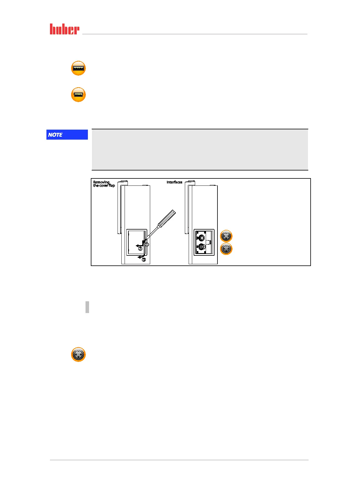
6.2.1.1 Removing the cover
PROCEDURE
Insert a screwdriver into the opening.
Prise of the cover to the left and away from you.
6.2.1.2 Jack ECS (External Control Signal) standby
Enable signal ECS (external control signal) for starting/stopping the temperature control process.
Activation via a potential-free contact. Contacts 1 and 3 are internally bypassed. ECS is energized
when E1 and E2 are connected by an external floating contact. Contact specification: min. 0.1 A /
24 V DC.
The functionality of the ECS is determined via the “Interfaces” category.
The following variants are offered:
▪ “No Action”: Switching the contacts open/closed or closed/open has no effect.
▪ “Switching to second setpoint”: A change from a closed to an open contact replaces the set
setpoint with the second setpoint. This altered setpoint is not fixed to the second setpoint but can
be changed by the operator at the temperature control unit at any time. A change from an open
to a closed contact does not cause any change and the temperature control process is not reset to
the original setpoint.
▪ “Second setpoint selective”: An open contact causes a thermoregulation to its original setpoint.
An closed contact causes a thermoregulation to the second setpoint.
Standard interfaces
at the “Unistat Con-
trol ONE” side.