42Cable Installation
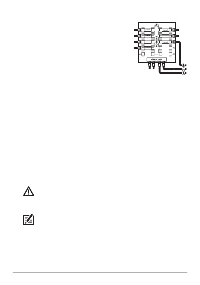
2a. Main Switch/Fuse Panel: If a fuse terminal is
available, use crimp-on type electrical connectors
(not included) that match the terminal on the
fuse panel. Attach the black wire to ground (–),
and the red wire to positive (+) 12 VDC power,
and the drain/shield wire to the boat’s chassis
ground terminal.
MEGA Live Imaging TargetLock: Install a 5A
slow-blow fuse (not included) for protection of
the unit.
MEGA 360: Install a 1 Amp fuse (not included)
for protection of the unit.
OR
2b. Battery Switch: Install the battery switch (not included) using the instructions
provided with it.
MEGA Live Imaging TargetLock: Install an inline fuse holder and a 5A slow-
blow fuse (not included) for protection of the unit.
MEGA 360: Install an inline fuse holder and a 1 Amp fuse (not included) for
protection of the unit.
Attach the black wire to ground (-), the red wire to positive (+) 12 VDC power,
and the drain/shield wire to the boat’s chassis ground terminal.
WARNING! If you are unable to obtain a battery switch and are forced to
connect the power cable directly to the battery, be aware that this will drain the
battery. Humminbird does not recommend connecting to a battery without the
appropriate fuse and a switch.
NOTE: The drain/shield wire is the non-tinned black wire.
3. Secure the cables along the route as needed for a clean assembly.
Connecting to the Fuse Panel