ii
Route the Cables and Connect Power 34
1. Route the MEGA Live Power, Ethernet and Heading Sensor Cables ..............34
2. Route the MEGA Live Control Box Cables ...........................................36
3. Route the MEGA 360 Cables (separate purchase) .................................. 40
4. Connect Power ........................................................................ 41
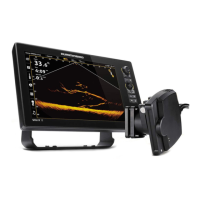
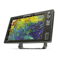
Set Up the Control Head 43
1. Confirm Connections ................................................................. 43
2. Set Up MEGA Live Imaging on the Control Head ................................... 46
3. Test MEGA Live Imaging on the Control Head ...................................... 47
4. Pair the TargetLock Heading Sensor to the Control Head .......................... 52
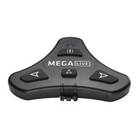
5. Pair the Foot Pedal to the Control Head ............................................. 53
6. Calibrate Your MEGA Live Imaging TargetLock ..................................... 55
7. Confirm the Humminbird GPS Heading Sensor Operation (optional) .............. 56
8. Confirm the Baud Rate (for devices connected to sensor pigtail only) ............. 59
9. Set Up the Network .................................................................. 59
Power Off 60
Maintenance 61
Control Head Maintenance ............................................................. 61
Transducer Maintenance ............................................................... 62
MEGA Live Imaging Maintenance...................................................... 62
Troubleshooting 63
“Out of the Water” Error Displays when MEGA Live is in the Water................. 63
Fishing System Doesn’t Power Up ..................................................... 64
Fishing System Defaults to Simulator with a Transducer Attached .................. 64
Finding the Cause of Noise ............................................................. 65
Specifications 66
Contact Humminbird 69
Table of Contents