INSTALLATION
20
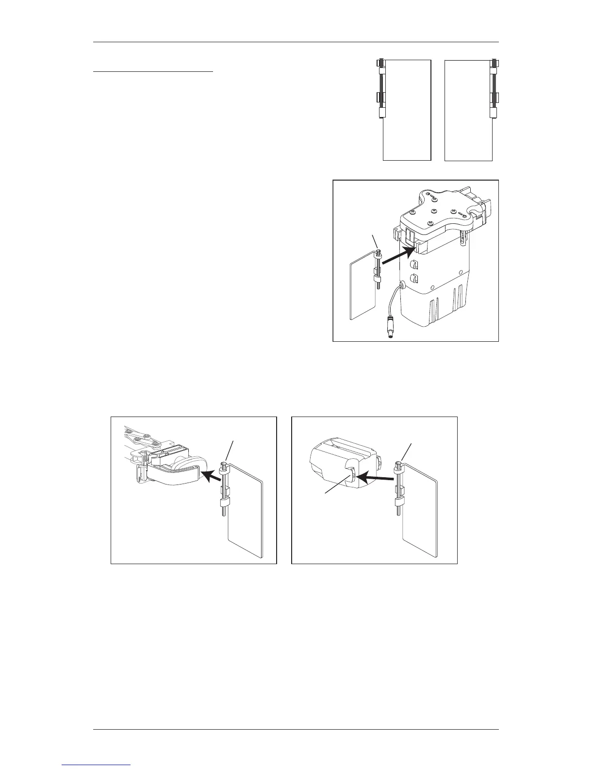
Swivel Plate Attachment
Swivel plates are right- and left-specific, marked by an R or
an L. The swivel plates are packaged with the product’s
hardware.
■ Snap the rivet on the swivel plate into the front
clip on the motor housing. Swivel plates attached
on the left will have STD L stamped on the top.
Swivel plates attached on the right will have STD
R on the top.
■ Snap the rivet on the other swivel plate onto the swivel arm (side stack) or into the front clip
on the non-control end cap (split stack). Swivel plates attached on the right will have STD R
stamped on the top. Swivel plates attached on the left will have STD L on the top.
STD R STD L
Rivet
STD L
Swivel Plate
Side Stack
Swivel Arm
Rivet
Swivel Plate
Split Stack
Rivet
Front Clip
Non-Control End Cap
STD
R
STD
R
 Loading...