3
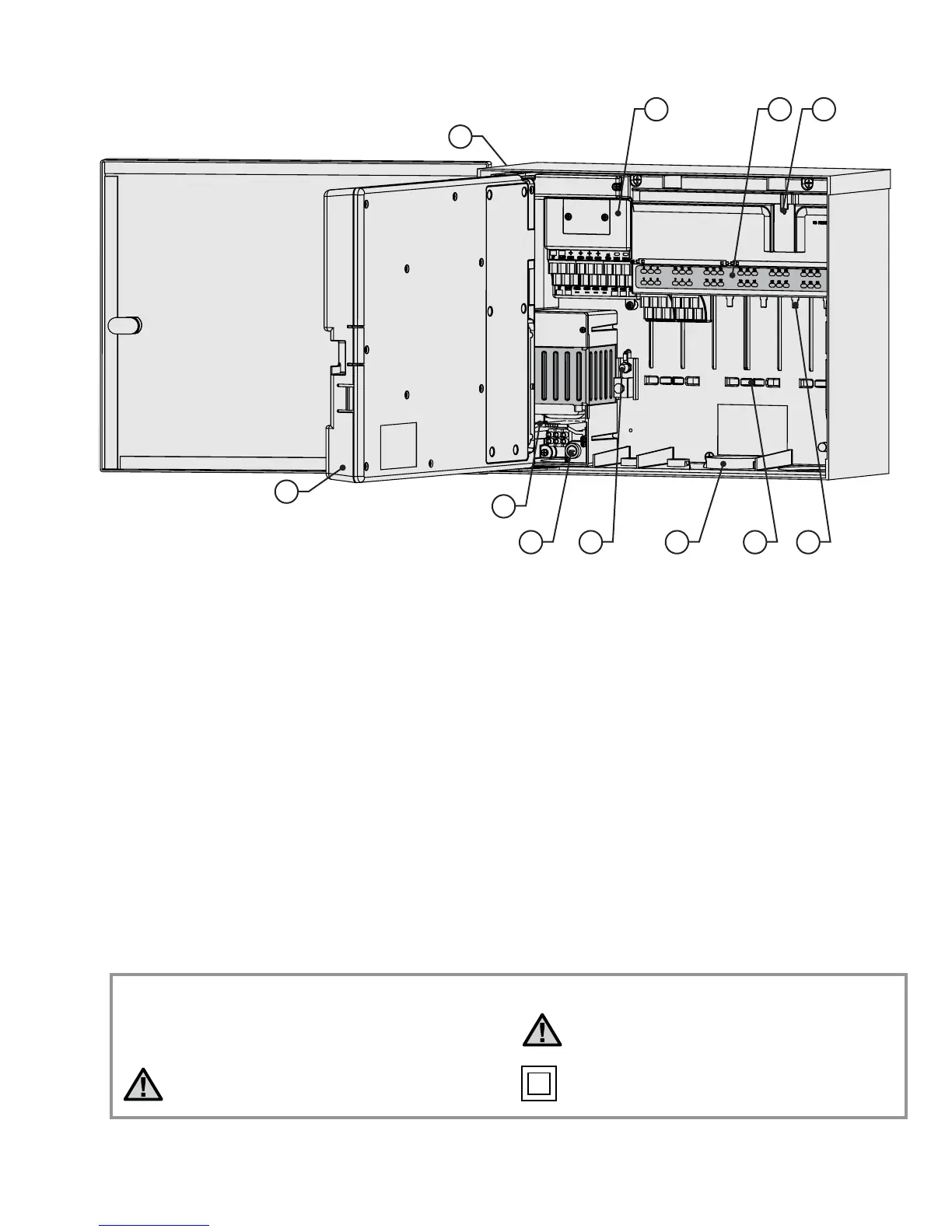
WIrInG ComparTmenT InTerIor ................................................
1. Inner Door – Opens to main wiring compartment
2. AC Wiring compartment – For connection of 120/230V
AC power with 1 x 0.75" (19 mm) conduit opening
3. Fuse – 2 Amp (fast) 250V, 6 x 20 mm
4. Conduit Openings, Low Voltage – 2" x 2½" (64 mm),
2" x ¾" (19 mm)
5. Wire Tie Holders for Valve Wires – Valve wiring area
6. Station Output Terminals (Valve Wires) – screw
terminals on 6-station output modules
7. Upper Deck Panel with Led Status Indicators –
Numbered station lights, green for active, red for faults
8. Sliding Lock for Output Modules – Permits addition
or removal of output modules, locks wired modules
in place
9. Master Module – Includes sensor, Pump/Master
Valve, and other accessory connections
10. SmartPort
®
– Integrated connector for ICR/SRR
receiver (on side of cabinet)
11. Earth Ground Lug – For connection of earth ground
copper wire (for surge protection only). Do not
connect valve commons – see Master Module for
Common wiring of solenoids and valves.
1
2
3 4 5 6
7 89
10
11
~
Explanation of Symbols
AC
Consult Documentation Double Insulated
Hazardous Voltage Present