11
CONNECTING STATION WIRES
1. Route valve wires between control valve location
and controller.
2. At valves, attach a common wire to either solenoid wire
of all valves. This is most commonly a white colored wire.
Attach a separate control wire to the remaining wire
of each valve. All wire splice connections should be
done using waterproof connectors.
3. Route valve wires through the conduit and attach conduit
to one of the openings on the bottom of the cabinet.
4. Strip ½" (13 mm) of insulation from ends of all wires.
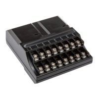
Secure the valve common wire to “COM” (Common) terminal.
Attach all individual valve control wires to the appropriate
station terminals.
COM
1
2
3
4
NOTE: The common terminal screw has
moved from the base module and is
now below the sensor terminals. Do not
connect the incoming common wires to
the P/MV terminal.

 Loading...
