1 2 3 4
Mini-Clik
Controller
C
Solenoid
Va
lves
Common Wire to
All Va
lves
Fig. 3
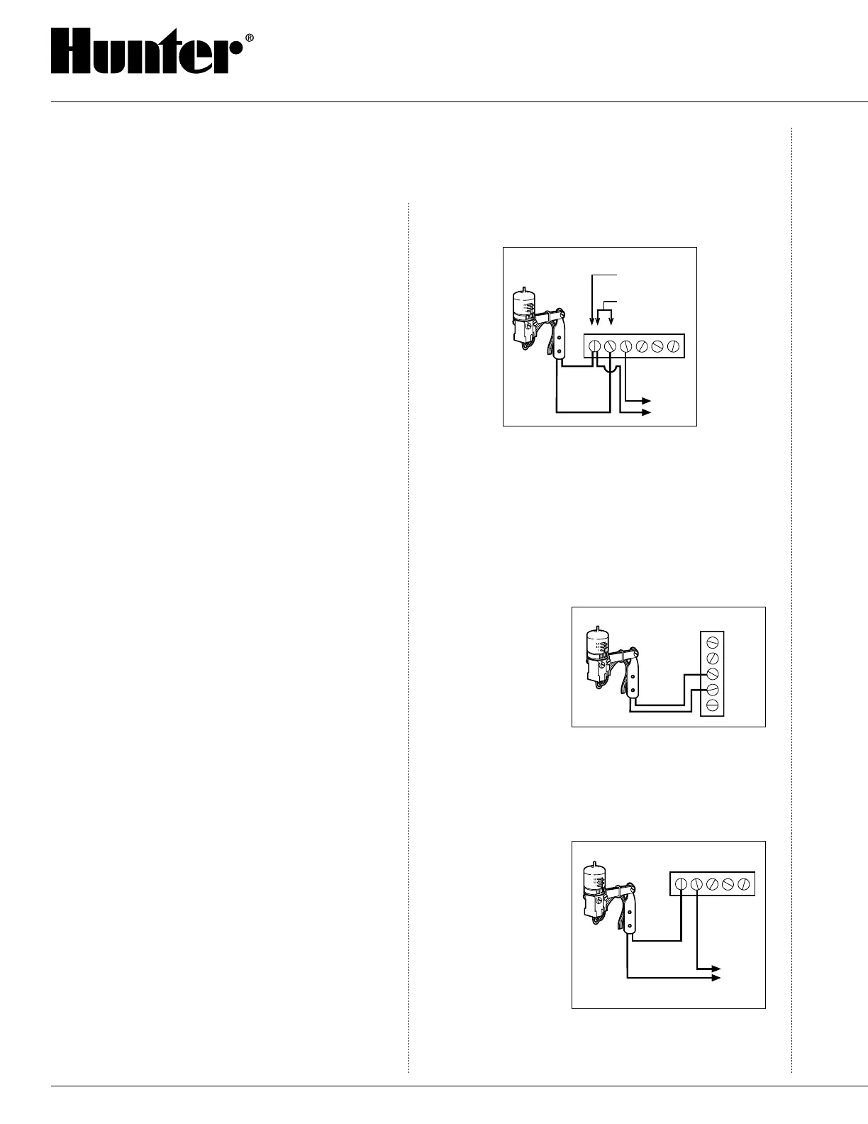
Mini-Clik
Pro-C or Hunter ICC
SEN
SEN
C
TEST
P MV
Fig. 2
16
C. As described in the “Operation” section of this
manual, “reset rate” refers to the amount of time
it takes the Mini-Clik
®
to dry out sufficiently for
the sprinkler system to be allowed to come back
on. The mounting location will affect this rate
and should be taken into consideration should
extreme conditions exist. For example, mounting
the Mini-Clik on a very sunny, southern end of a
building may cause the Mini-Clik to dry out sooner
than desired. Similarly, mounting on the northern
end of a building with constant shade may keep the
Mini-Clik from drying soon enough.
Once the Mini-Clik is mounted, run the wire to the
controller, and fasten it every few feet with wire clips
or staples for best results. If an extension to the wire
provided is needed, use the following table to deter-
mine the minimum wire gauge needed:
If the extension needed is:
25-50 feet use: 20 gauge
50-100 feet use: 18 gauge
100 feet or more use: 16 gauge
Wiring To Your Irrigation System
Important: The Standard Model Mini-Clik is sold and
designed for hook up to 24 Volt irrigation controllers
only. For wiring to 110V or 220V irrigation controllers,
please consult your distributor or Hunter Industries
Data Line at 800-733-2823. All wiring must conform
to National Electrical Code or applicable local codes.
For the Model Mini-Clik-C: WARNING! This unit
is designed to be installed in conjunction with 24VAC
circuits only. Do not use with 110 or 220VAC circuits.
For the Model Mini-Clik-HV: WARNING! This unit
must be installed by a qualified electrician in accor
-
dance with National Electrical Code and applicable
local codes. The electrical rating of this device is
125-250VAC at 10.1 amps. Do not let current pass
through this device that exceeds this rating. Do not
install directly in line with any pump.
Wiring to the Hunter SRC Controller
The Mini-Clik connects directly to the SRC. This
allows you to easily override the sensor by using the
RUN (BYPASS SENSOR) position on the dial.
1. Route the wires from the Mini-Clik up through the
same opening used for valve wiring.
2. Connect one wire to the RS terminal and other to
the C terminal (See Fig. 1).
3. Connect the valve common to the RS terminal.
1 2 3 4
Mini-Clik
Hunter SRC
CRS
Connect Common to
this Terminal when
using Rain Sensor
Connect Rain
Sensor Wires to
These Two Terminals
Solenoid
Va
lves
Fig. 1
Wiring to the Hunter ICC, Pro-C or
EC Controller
The Mini-Clik connects directly to the EC, ICC or
Pro-C. This allows you to easily override the sensor by
using the Sensor switch on the front panel.
1. Remove the jumper from the two “SEN” terminals.
2. Route the wires from the rain sensor up through the
same conduit opening used for valve wiring.
3. Connect one wire
to the terminal
labeled “SEN”
and the other
wire to the other
“SEN” terminal
(See Fig. 2).
Other Controllers
The two most common situations are shown below.
For non-standard wiring situations, please consult your
distributor or request our “non-standard” wiring infor-
mation packet.
A. 24 Volt Solenoid
Valves Only (No
booster pump)
(See Fig. 3).
With the two
wires from the
Mini-Clik at the
controller, locate
the “common
ground” wire of
the solenoid valves. If it is connected to the com-
mon terminal on the controller, disconnect it. Attach
one wire of the Mini-Clik to the “common” terminal
INSTALLATION INSTRUCTIONS (continued)

 Loading...


