Normally-
Open Relay
1 2 3 4
Controller
C
Solenoid
Va
lves
Common
Wire to Al
l
Va
lves
Mini-Clik
Pump
or MV
Line-In
Line-Out (to Pump)
Fig. 4
Controller
110V
Soleniod
Valves
110V
Input
110V
Switched
Input
110V Line
Mini-Clik-HV
Fig. 5
Controller
Switched
Output
Input
Mini-Clik-HV
220V to Pump
Normally
-
Open Relay
Line-In
Coil
Fig. 6
1/8
1/4
1/
2
3/4
1
VentVent Ring
Fig. 7
17
(usually marked “C”) on the controller. Attach the
other wire of the Mini-Clik
®
to the common wire
leading to the valves. Note: The common wire to
the valves does not have to be interrupted at the
controller. The Mini-Clik may be wired anywhere
along the common wire line.
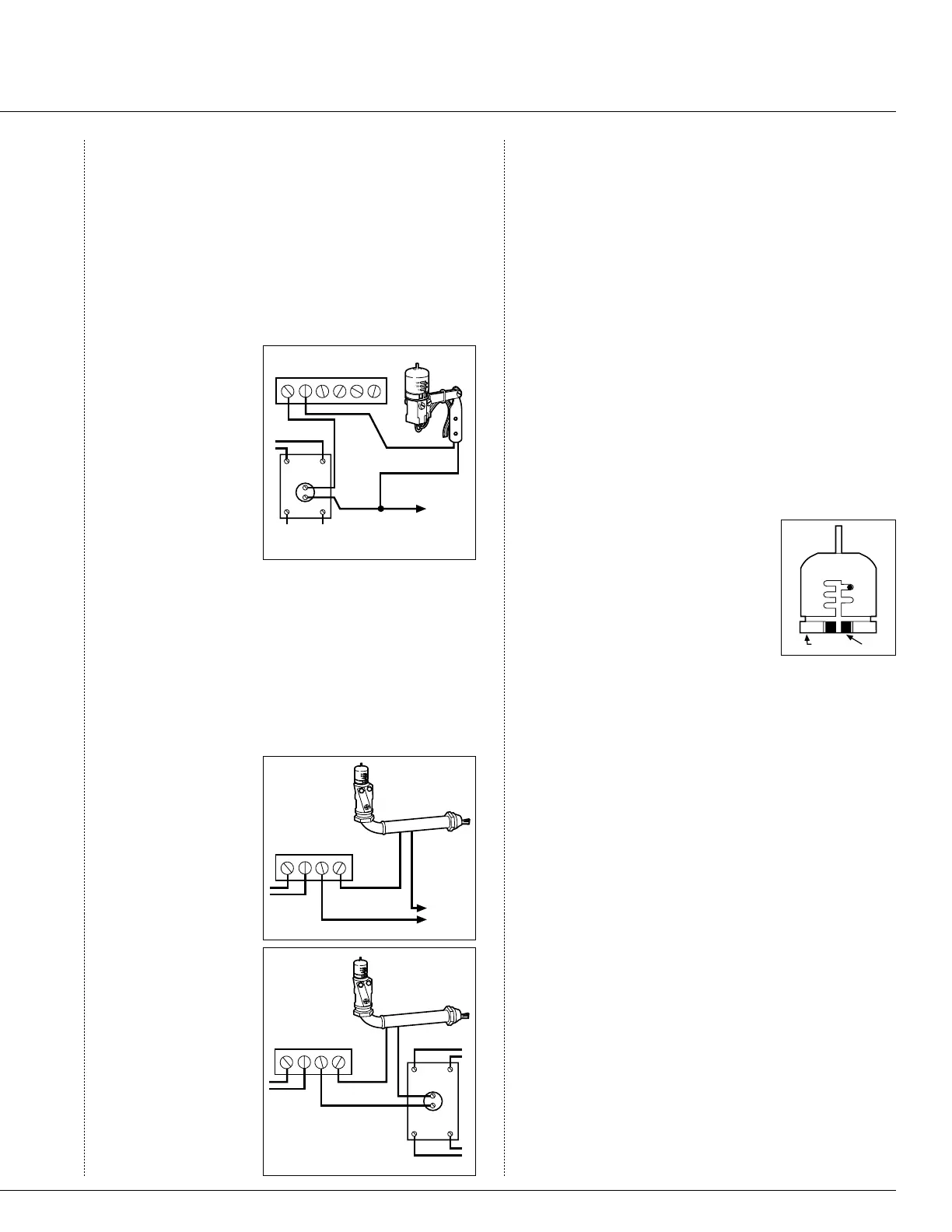
B. 24 Volt Sole
-
noid Valves with
Booster Pump
(See Fig. 4)
Locate the com
-
mon wire to the
solenoid valves
and the common
wire leading to the
coil of the relay
that starts the
pump. If these two wires are connected to the “com-
mon” terminal on the controller, disconnect both
of them.
Twist together these two wires along with one wire
from the Mini-Clik, and secure with a wire nut.
Attach the other wire of the Mini-Clik to the “com-
mon” terminal on the controller. Note: The pump
circuit output must be 24 Volts in this situation.
Do not proceed if 110V.
C. Special In
-
structions for
Mini-Clik-HV
(See Fig. 5 and 6)
The two taped
and stripped wires
are the ones to be
used when follow-
ing these accom-
panying diagrams.
All wire connec-
tions with the
Mini-Clik should
be made with wire
nuts and located in
a junction box.
Where the timer
is controlling a
pump, the relay
may be inside the
timer, external,
or non-existent. If there is no relay in the circuit,
one must be added. The wiring for an internal or
external relay is the same: The Mini-Clik breaks the
circuit to the coil of the relay only. Either wire of
the coil may be broken.
Operation Check to Verify Correct Wiring
Turn on one zone of the irrigation system that is vis-
ible while you are in reach of the Mini-Clik. Manually
depress the spindle at the top of the Mini-Clik until you
hear the switch “click” off. The sprinkler zone should
stop instantaneously. If it does not, check to see if it is
wired correctly.
Adjustments and Operation
The Mini-Clik can keep the irriga-
tion system from starting or continu-
ing after rainfall quantities of
1
⁄
8
",
¼", ½", ¾" or 1". To adjust it to the
desired shut-off quantity, rotate the
cap on the switch housing so that the
pins are located in the proper slots
(see Fig. 7). Do not forcibly twist
the cap as this might break the pin.
The time that it takes the Mini-Clik to reset for
normal sprinkler operation after the rain has stopped
is determined by weather conditions (wind, sunlight,
humidity, etc.) These conditions will determine how
fast the hygroscopic discs dry out, and since the turf is
also experiencing the same conditions, their respective
drying rates will roughly parallel each other. So when
the turf needs more water, the Mini-Clik is already
reset to allow the sprinkler system to go at the next
scheduled cycle.
There is an adjustment capability on the Mini-Clik
that will slow down the reset rate. By turning the “vent
ring” (see Fig. 7) to completely or partially cover the
ventilation holes, the hygoscopic discs will dry more
slowly. This adjustment can compensate for an “overly
sunny” installation location, or peculiar soil conditions.
Experience will best determine the ideal vent setting.
Mini-Clik
®
Sensor

 Loading...


