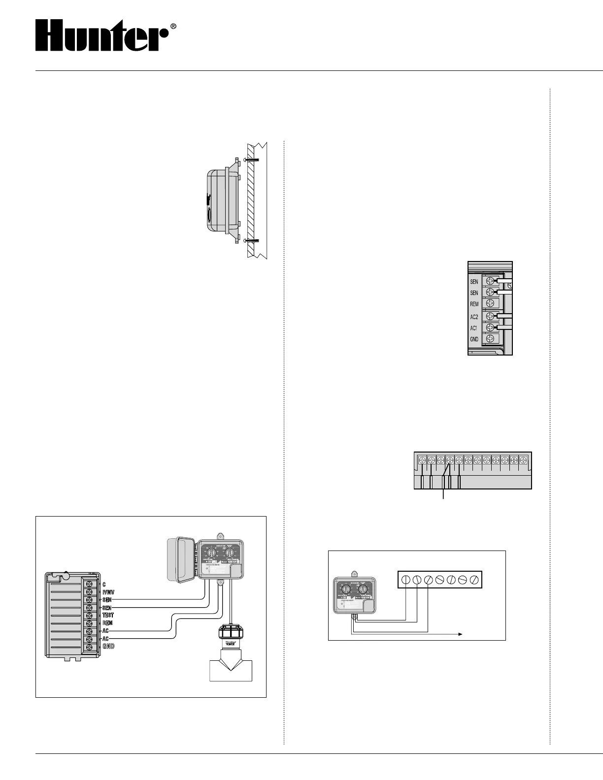
Hunter Controller
Power Module (Typical)
Flow-Clik Interface Box
Flow-Clik Sensor
Sensor Loop
White
White
Yellow
24 VAC Powe
r
Yellow
AC AC R RS C MV 1 2 3 4 5 6
Yellow White
Valve
Common
White
White
Yellow
Yellow
To Sensor
30
Interface Box. A lock is also provided to prevent
unauthorized changes in Flow-Clik™
settings. There are two mounting tabs
on the top and bottom of the Interface
Box to provide an easy means to secure
it on the wall next to the controller.
Using the hardware included, mount
the Interface Box to the wall (use screw
anchors if needed). Make sure to place
the Interface Box close to the controller
(check that the controller door and Interface Box door
to not interfere with one another).
Wiring The Flow-Clik To The
Irrigation System
WARNING! This unit is designed to be installed in
conjunction with 24 VAC circuits only. Do not use with
110 or 220 VAC circuits.
Wiring the Sensor to the Interface Box
The red and black leads from the Flow-Clik sensor
are connected to the red and black leads on the In-
terface Box. A minimum wire size of 18-gauge wire
can be used to connect the leads from the sensor to
the Interface Box. Secure all wire connections with
waterproof connectors.
It is recommended that the red and black leads from
the Interface Box be routed into the controller. Wire
connections for the sensor can be made inside the con-
troller cabinet.
Note: The Flow-Clik Sensor can be installed up to a
maximum of 1,000 ft. from the Interface Box when
installed with #18 gauge or larger copper wire.
Wiring the Interface Box to the Controller
Hunter controllers have provisions for sensor installa-
tions that allow for easy wiring of the Flow-Clik to the
controller. The two white wires from the Interface Box
are attached to the sensor terminals inside the control-
ler and the two yellow wires are attached directly to a
constant 24-volt source.
To wire the Flow-Clik Interface Box on
Hunter controllers:
Pro-C, ICC and EC Controller
Installations
1. Attach the two yellow wires to
the AC terminals on the controller
(polarity does not matter).
2. Attach the two white wires to the
SEN terminals on the controller.
SRC Controller Installations
1. The two yellow wires are connected to the AC ter-
minals on the controller (polarity does not matter).
2. Attach one of the two white wires to the RS termi
-
nal on the controller.
3. Attach the other white wire to the “C” terminal.
4. Attach the valve com
-
mon and pump relay
common (if used) to
the RS terminal.
Other Controllers
1. Attach the two yellow wires to the AC terminals on
the controller (polarity does not matter).
Interface Box
Common Wire
to All Valves
Y
W
Y
W
1 2 3 4
Controller
CAC AC
2. Some controllers do not have terminals dedicated
for sensor installations. Locate the common wire
to the solenoid valves and disconnect it from the
common terminal (usually marked “C” on the con-
troller). Attach one white wire from the Flow-Clik
Interface Box to the common terminal. Attach the
other white wire to the common wire leading to
the valves.
INSTALLATION INSTRUCTIONS (continued)

 Loading...


