always goes from the guide wire to the left in the
connection between guide wire and boundary loop.
The strength of the guide signal varies like the A signal
depending on the distance to the guide loop. Inside the
guide loop the signal is positive and the strength
subsequently diminishes the farther away from the wire
you get. Outside the guide loop, the signal is negative
and the strength of the signal diminishes more rapidly.
Note: The product always tracks the left side of the
guide wire when facing the charging station, i.e. the
product follows the negative values on the guide signal.
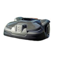
CAUTION: Do not lay the guide wire at 90°
angles or less. Lay the wire in two 135° angles.
3.6 Charging station
The placement of the charging station must be well
planned in order to give the best installation and
operation of the product. Refer to
To examine where to
put the charging station
in the Operator’s Manual.
Note: The battery is spared if charged in low ambient
temperature, but not below freezing. Consequently, it is
beneficial if the charging station is placed where it is
shaded, especially during the warmest parts of the day.
When the battery level has dropped to 600 mAh or the
battery voltage has dropped to 17.25 V, the product
shuts down the cutting motor and starts searching for
the charging station.
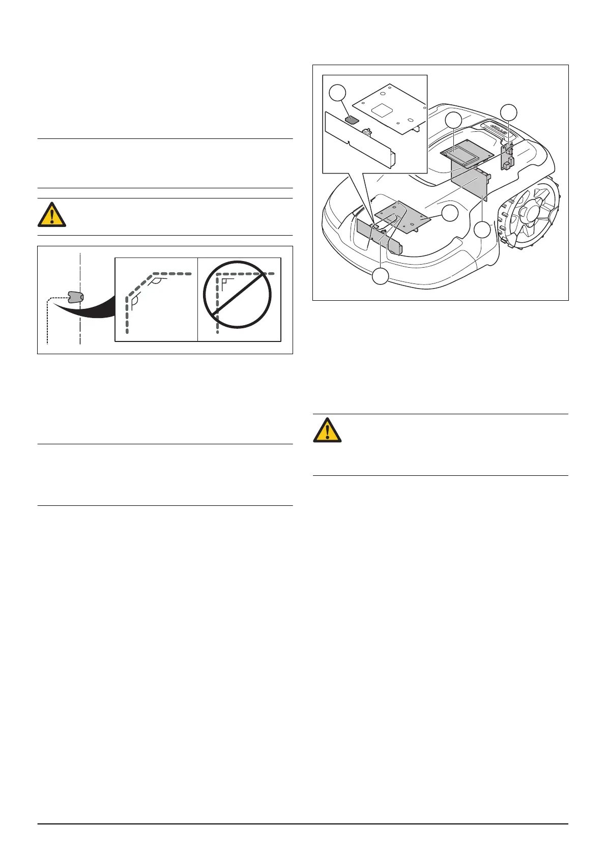
3.7 Circuit boards and sensors
The circuit boards and sensors in the product:
1. Motor control circuit board (tilt sensor)
2. Communication circuit board
3. Rear loop sensor circuit board (rear loop sensor and
stop sensor)
4. Front loop sensor circuit board (front loop sensors)
5. Application circuit board
6. Front lift sensor / magnetic sensor circuit board (lift
sensor)
CAUTION: Some sensors contain a hall sensor
and a magnet. Because of the magnets south
and north pole, it is important that the magnet is
correctly installed.
3.7.1 Tilt sensor
The tilt sensor is a sensor on the motor control circuit
board that detects the product's inclination in relation to
the horizontal plane. The X-angle indicates front to rear
inclination, and the Y-angle indicates left to right
inclination. The value from the tilt sensor is used, among
other things, to correct the speed of the drive wheels
when mowing in steep slopes.
3.7.2 Lift sensors
The lift sensors detect if the product is being lifted off the
ground. This is done with the help of the mechanical
design and magnets. If a lift signal is indicated, the blade
disc stops immediately. The product tries extrication
maneuvers by reversing and turning several times.
3.7.3 Loop sensors
The loop sensors measure the signals that the charging
station sends through the boundary loop (A signal), the
guide loop (Guide signal) and the baseplate (F signal).
The signals are used to control the product and keep the
product inside the work area. The product can only
1582 - 001 - 23.12.2020 Product and installation - 7
 Loading...