13
Installation (Cont'd)
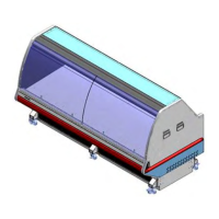
Channel Weldment Assembly
(Left Wing Channel Shown)
1) Refer to the critical measurements section of the instructions for reference dimensions. (Page 16)
2) Check Position
• Hinges over outer side of end panel
• Holes on outer side of end panel
• Be Sure the left weldment is installed on left end
2) Place channel on end panel to the recommended speci! cation
3) Use a rubber hammer to work channel over T- molding
• Trim the T-molding if necessary
4) When recommended and/or optimal position is found, use the wood screws to secure channel to the end panel
Note: The Optimal Position will be within the recommended range
Note: It may be necessary to adjust the Wing Channel Weldment to optimize the ! t and position.
Do not fasten Channel until this step is complete.