3.24
A
D
C
F
B
G
E
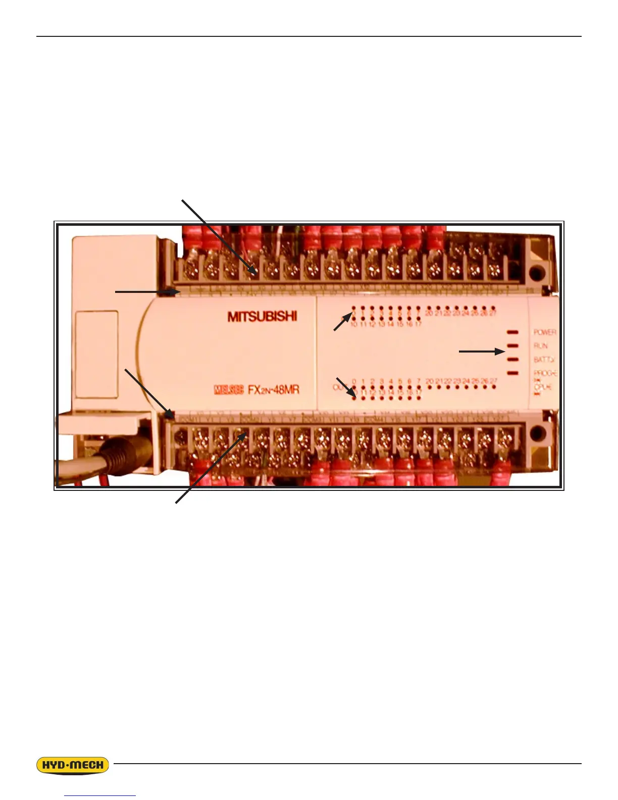
MITSUBISHI FX2N 48MR INPUTS & OUTPUTS
A - input terminals E - output indicating LED ‘s
B - input indicating LED’s F - output terminal identication
C - input terminal identication G - PLC status indicator lights
D - output terminals
Input and output terminal identication:
- The top row of identication labels corresponds to the top row of terminals and the bottom row of labels to the bottom
row of terminals.
Input and Output LED numbers correspond to the Input or Output of the same number.
i.e. Input LED #0 corresponds to Input X0 . Output LED #0 corresponds to Output Y0
PLC Status indicators:
Power - on when power exists to the PLC
Run - on when the PLC is running
Batt V - on when PLC memory backup battery has low voltage condition
Prog E - on when PLC has a program error.
DIAGNOSIS:
1. Check for LED light on the sensor - light on indicates prox. sensor power connections are correct and sensor is
activated. Problem could be with the sensor, signal wire to the PLC or with the PLC. With blade running, proximi-
ty LED should pulse. Likewise, the PLC input LED (X2) should be pulsing. If both LED’s are pulsing with the blade
running, the PLC is the problem. If the sensor LED is pulsing but the input (X2) LED is not; there is a problem
between the sensor and the PLC input (X2) terminal.
• If the LED on the sensor is not on, the problem is with the sensor wiring or the sensor is at fault.



 To Next Page