12
The clearance between the O.D. of the bar and the remainder of the liner or liner
bushings should be approximately 0.5 mm over the bar O.D. and the effective length
of the support bushings should not be greater than 25mm, except with very small
diameter bar, i.e. 5mm diameter or less. Chamfers on each end of the bushings
should be long enough to reduce the effective length of support as short as 20mm
long.
These conditions will ensure that the bar, which is outside of the lathe spindle, will be
rotating as accurately as possible so to avoid ‘whip’ and prevent vibration caused by
eccentric rotation.
It should be understood that if the length of bar is not true, i.e. bent, this will cause
problems dependant on the degrees of trueness.
The Bar Support Unit is not effective when machining hex or square bar and bar
lengths should be restricted to 1 metre.
If plastic material is being run in the Bar Support Unit, do not use standard oilon
bushings, but use steel bushings in the Bar Support Unit.
4.3. FITTING MASTER REDUCTION LINER INTO THE LATHE SPINDLE AND
SELECTING THE CORRECT SIZED BORED BUSHINGS
Fit the master spindle reduction liner with the correct size bushings into the
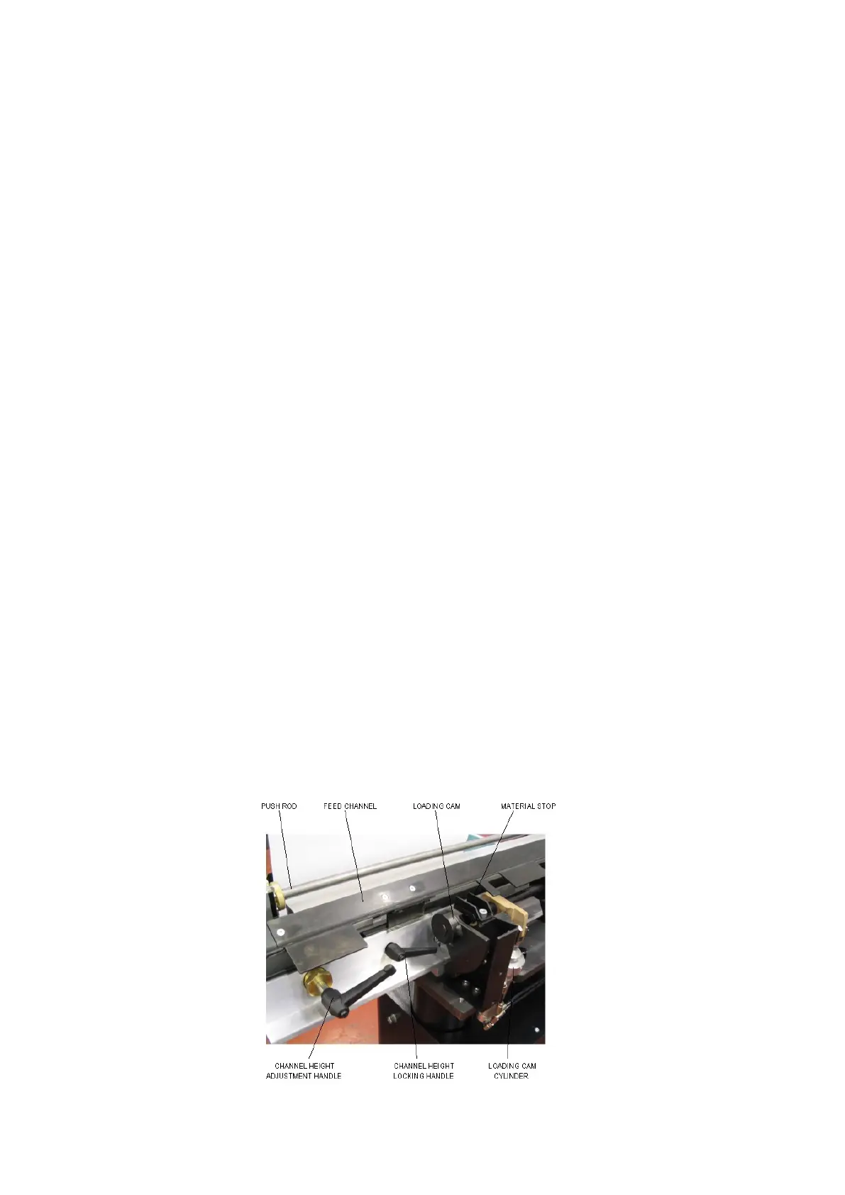
drawtube/spindle, lowering the support channel to obtain maximum clearance.
A handle that’s shown in diagram below will adjust the channel height.
The push rod that’s fitted to the Barfeed may be the same diameter as the bushing
bore, if this is the case it may be necessary to use a push rod that’s smaller in
diameter. This will prevent contact with the spindle wall and therefore vibration.
Where a small diameter push rod is used, it may also be necessary to use full retract
mode as the push rod may droop excessively when fully extended resulting in
vibration.
Figure 10
 Loading...