24
Note; if the sensor alarm is to keep generating then contact us quoting the
problem and the part n
o
.
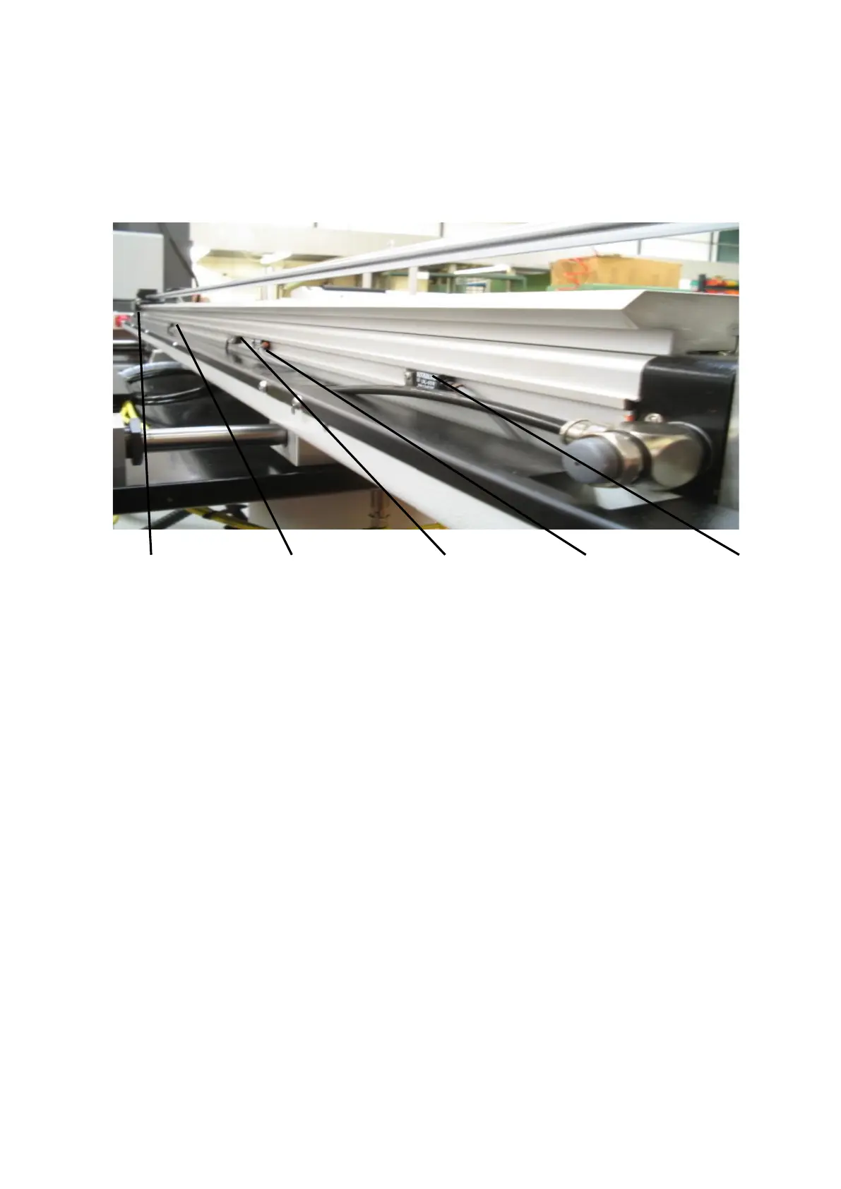
5.6 LOCATION OF CYLINDER SENSORS
Figure 25
Sensor 1 Sensor2 Sensor3 Sensor4 Sensor5
Pusher Home Mis-load Last Component Eject Remnant Pusher
E.O.B Forward
Picture of sensor may not be same as on machine.
Sensor 1
Pusher Home: this sensor is set directly below the Pusher carriage and is actuated
when Pusher is in its fully back position (home position) then checked on installation
and MUST not be moved after.
Sensor 2
Mis-Load: this sensor is positioned for shaped bar.
When loading shaped material into the collet section the bar has a tendency to catch
the rear of the collet/chuck due to it being bowed or buckled.
When setting this sensor: load the shortest bar that’s been cut, insert it into the collet
section then disconnect the air supply and manually push the Main Push rod behind
the back of the bar and feed to the rear of the collet/chuck.
Set the Mis-load sensor directly below the Pusher carriage so that the LED
aluminates on the sensor, secure the sensor at this position then re-connect the air
supply.
When Barfeed is in auto operation and reloading bar takes place the bar is checked
when feeding it through the collet/chuck, if the bar becomes jammed behind the
collet/chuck the Main Push rod will pulse up to eight times whilst the Spindle is
slightly rotating, this will encourage the bar to be fed through the collet/chuck.
If the bar is unable to feed through the collet/chuck after 8 attempts the Barfeed will
generate an alarm to the Lathe and stop pushing.
 Loading...