32
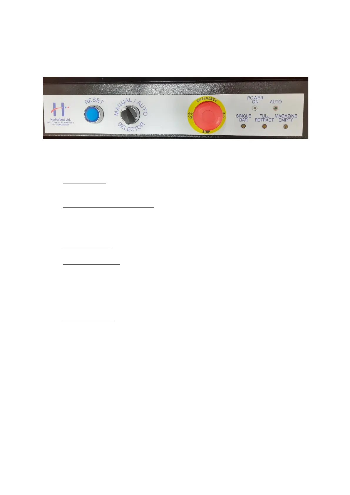
9.1 CABINET CONTROL FUNCTIONS
Figure 40
BLUE REST LIGHT MUST BE OFF WHEN BARFEED IS IN USE
9.1.1 Auto indicator; when the manual/auto is selected to auto and the safety circuit
is ready this indicator will illuminate and in turn generate an auto ready signal
to the Lathe
9.1.2 Warning/Condition indicators; these indicators represent the condition status
that’s described above the individual neon. (See page 34-35)
They also represent warning and alarm conditions and which are defined, as
all three neon’s illuminating together ie simultaneously, sequentially or
permanently. (See page32)
9.1.3 Power indicator; this simply signifies that mains power is applied to the
Barfeed.
9.1.4 Man/Auto selector; when the Barfeed is in Manual mode with the safety circuit
ready, the functions of the Barfeed are operable by the hand control unit,(see
page 34).
When the Barfeed is selected to auto this will engage the Barfeed to auto
initialisation, then pressing the button on the hand control unit it will generate
the auto ready condition. (See page 34)
9.1.5 Emergency stop; this switch is an integral part of the Barfeed’s safety circuit,
the switch is designed so that when the button is pressed it will latch in the
down position and in turn will disable the Barfeed’s functions from operation.
On releasing the button the Barfeed will re-engage the functions.
NOTE; Barfeed Emergency stop – Barfeed Hood – Lathe Emergency stop
are the main elements to the safety circuit, the Emergency stop’s are to
be released and the Barfeed’s hood is to be closed before the safety
circuit is enabled.
 Loading...