S
shepherdhannahAug 2, 2025
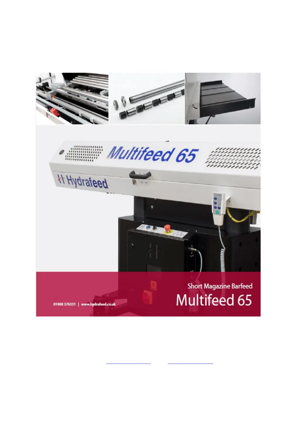
Why is my Hydrafeed Multifeed 65 not referencing?
- RRichard KennedyAug 3, 2025
Several factors can prevent your Hydrafeed Industrial Equipment from referencing. First, ensure the air pressure is at least 60psi. Also, verify that the Emergency Stop is released on both the Barfeed and Lathe after ensuring safe application. Confirm that the Man/Auto switch is in manual mode. Finally, check that the home sensor is active by inspecting input X11 (the sensor below the carriage) for any faults.