6
2. INSTALLATION
When this instruction manual was printed, the information given was correct.
However, since we are constantly improving the design of our Barfeed’s, it is possible
that the illustrations and descriptions may vary from the Barfeed supplied.
When supplied for installation within Europe, the Barfeed carries the CE mark of
incorporation, and should be declared in conformity with the EC Directives after safe
installation with the Lathe.
Site Preparation
3.0 Ensure that the Lathe is secured in position on solid flooring by means of either
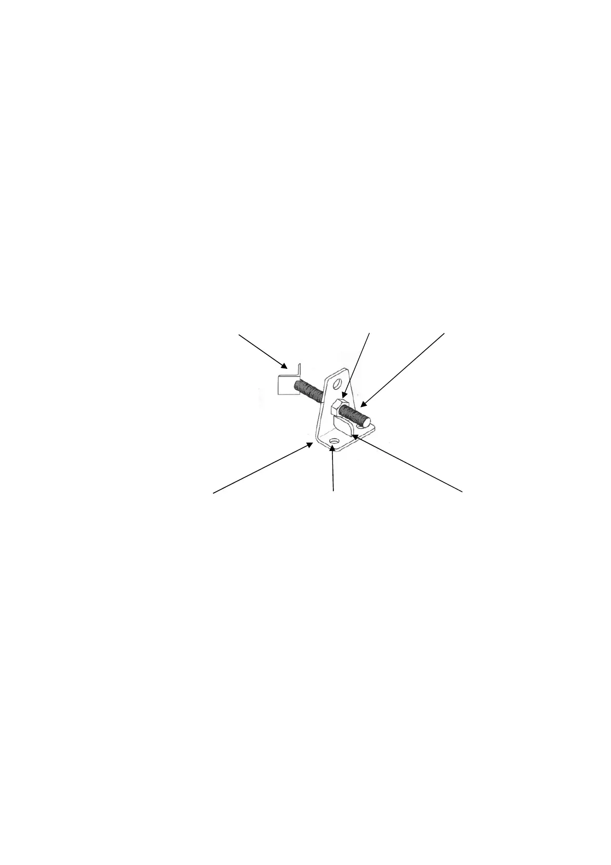
floor bolts through Lathe feet, or by Restraining Brackets, illustrated in figure 30.1.
40x40x5 Angle Iron 2-off M20 Lock Nuts M20 Studding
Figure 30.1
6mm Bracket 16.5 Holes for Floor Fixing Reinforce Rib
Diagram 30.1 is a typical example of a restraining bracket; items of similar design
should be used to prevent Lathe movement where it has not been possible to secure
the Lathe through its feet.
3.1 Ensure that the Lathe is accurately levelled in all planes using a machine level.
3.2 Check that the Lathe has been correctly interfaced to the Barfeed control
specification.
3.3 Ensure sufficient space (foot print) is available for the Barfeed to be positioned
next to Lathe! Allowing for the space required for the swing aside facility in front of
the Barfeed and also taking into consideration space required for access when
loading the magazine. Complete requirements illustrated in figure 30.2
 Loading...