34
9.2 ALARM SIGNALS
ALARM DISCRIPTION
Alarms remain active until the problem is cleared, the machine will not operate until
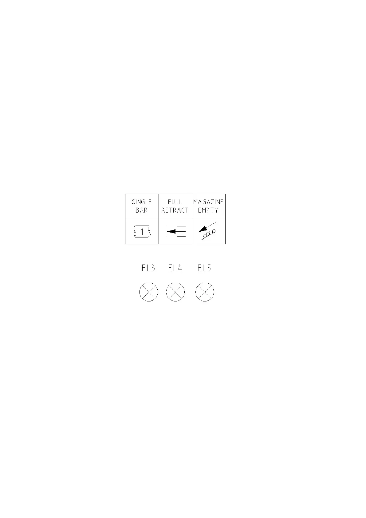
the cause of the alarm is removed. The three LED’s which are mounted on top of the
control cabinet indicate alarms and conditions.
Conditions are indicated when LED’s illuminate (either ON or FLASH)
independently.
Alarms are indicated when all three LED’s illuminate simultaneously.
Following list indicates their alarm fault conditions;
Figure 41
9.3 LIST OF ALARM SIGNAL MESSAGES
All three LED’s flash simultaneously
1. Loader sensor error. (See; Location of Material sensor)
2. Enable disengaged and Chuck is open
All three LED’s stay permanently illuminated
1. Input X5 Safety circuit off
All three LED’s flash sequentially
1. Timing out between M-Codes
2. Insert Pusher not reached full stroke
3. Pulsing Push rod count completed. (Eight times before alarming)
 Loading...