18
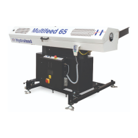
Move the stops so that the material is against the stops in the position shown in
figure 13.
Then adjust the stops so that only one piece of material is lifted into the V-channel.
Once this has been established be sure to tighten the stop screws securely.
Figure 13
Cam Adjustment stops Cam lever
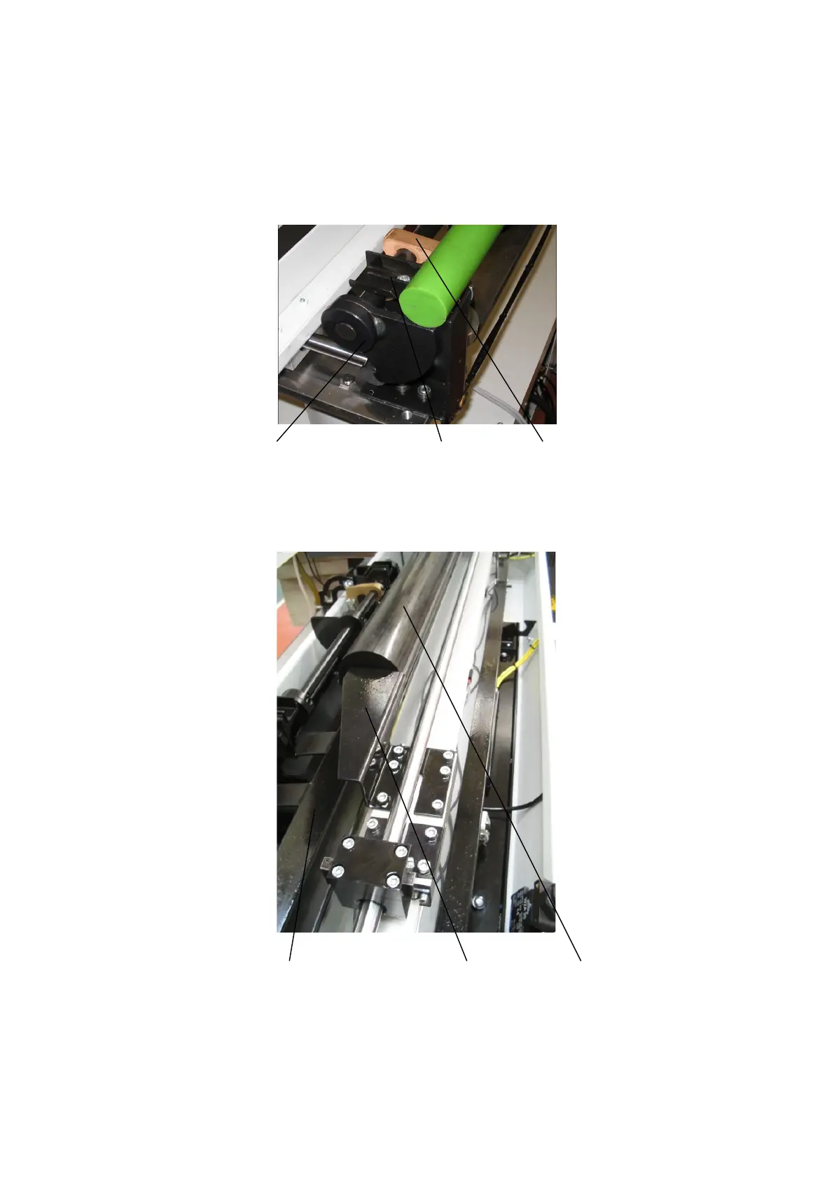
Figure 14
Material Channel Insert Pusher Material
The bar will remain stationary on the channel and the cross slide will be in the
position where the centre of channel is aligned with centre of spindle, either by
loading bar via hand control or through automatic reloading, figure 04 illustrates how
this is carried out.
 Loading...