8
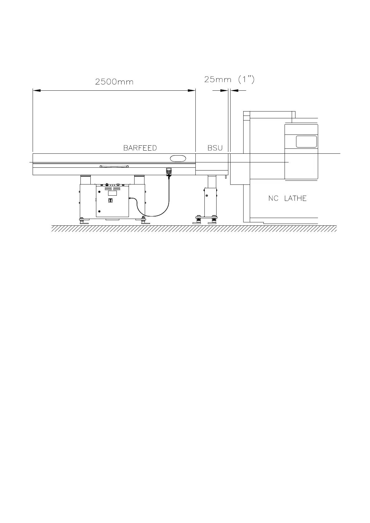
Figure 30.3
3.24 Open the cover on the Barfeed and remove the black plastic transit spacers
from the cross slide bars, then close the cover.
3.25 Connect air supply via filter bottle located at side of stand
Note; Minimum air supply 70psi(5bar).
3.26 Check the transformer settings and the voltage output from the Lathe, if these
are specified for correct interface proceed to stage 3.27, otherwise contact the Lathe
agent for alterations.
3.27 Connect the interface lead between the Lathe and the Barfeed.
3.28 Power up the Barfeed by turning the isolator located to the top right hand side of
the control cabinet to ‘ON’ the Barfeed will now reference its home position and will
be indicated on the screen when referencing is complete.
3.29 Power down the Barfeed then raise the cover of the Barfeed and remove the
Push Rod, the Push Rod is latched in two places;
i. De-latch the brass bushing from the support block that is positioned Lathe
side of Barfeed.
ii. The Push Rod is now to be released from the support blocks opposite side
to the brass bush, there is two latches which are to be arranged-refer to
Removing Push Rod in section 4.4.
Multifeed
 Loading...